Summary of Contents for 530 Series

Page 1: ...mps an overview 8 6 Warranty 9 7 Safety notes 11 8 Pump specifications 15 8 1 Specification ratings 15 8 2 Weights 15 8 3 Pumphead options 16 9 Good pump installation practice 17 9 1 General recommend...

Page 2: ...UNCTION Manual mode only 33 17 Flow calibration 34 17 1 Setting the flow calibration 34 18 MemoDose mode 37 18 1 To configure MemoDose 37 18 2 Set flow rate 38 18 3 Resume interrupted doses 39 18 4 Ma...

Page 3: ...9 25 1 Pump part numbers 79 25 2 Tubing and element part numbers 80 25 3 Pumphead spares 84 25 4 Pumping accessories 86 26 Performance data 88 26 1 Performance curves 88 27 Trademarks 93 28 Disclaimer...

Page 4: ...ective 2006 42 EC EMC Directive 2014 30 EC ROHS Directive 2011 65 EU 6 Harmonised standards used BS EN61010 1 2010 third edition Safety requirements for electrical equipment for measurement control an...

Page 5: ...uality Management System ISO 9001 and the technical documentation is compiled in accordance with Annex VII B of the Directive We undertake to transmit in response to a reasoned request by the appropri...

Page 6: ...pplied 530 Components 530 pump drive unit fitted with 520R2 or other pumphead if specified as a pump The designated power cable attached to the pump drive unit A 530N module providing pump ingress pro...

Page 7: ...us this information and receive a RGA Returned Goods Authorisation before you despatch the product s A copy of the RGA form must be attached to the outside of the packaging containing the product s Pl...

Page 8: ...track the second continues to advance expelling the packet of fluid through the pump s discharge port At the same time a new partial vacuum is created behind the second roller into which more fluid is...

Page 9: ...rectly or indirectly related to or arising out of the use of its products including damage or injury caused to other products machinery buildings or property Watson Marlow shall not be liable for cons...

Page 10: ...Failure caused by incorrect or sub standard system wiring is excluded o Damage by chemical attack is excluded o Ancillaries such as leak detectors are excluded o Failure caused by UV light or direct s...

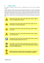
Page 11: ...with the Health and Safety at Work Act 1974 This symbol used on the pump and in the manual means Caution refer to accompanying documents This symbol used on the pump and in the manual means Do not all...

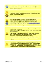
Page 12: ...s with the same rating There are no user serviceable fuses or parts inside this pump Note the mains power supply cable is supplied hardwired into the pump and is not customer replaceable IP66 pumps ar...

Page 13: ...Auto restart feature is enabled it may cause the pump to start as soon as power is turned on Auto restart only affects operation of manual mode network mode and memodose mode If Auto restart is enable...

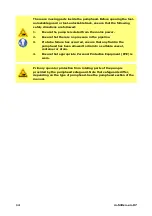
Page 14: ...ressure in the pipeline 3 If a tube failure has occurred ensure that any fluid in the pumphead has been allowed to drain to a suitable vessel container or drain 4 Ensure that appropriate Personal Prot...

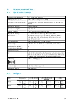
Page 15: ...Richtlinien m ssen gew hrleistet sein Full load current 530 0 6A 230V 1 25A 115V Fuse rating 530 Ceramic 5x20mm 2 5A 250V AC Time Delay Installation category overvoltage category II Pollution degree...

Page 16: ...ard Health and Safety guidelines Finger recesses are built into the sides of the lower shell for convenience in lifting in addition the pump can conveniently be lifted by grasping the pumphead and whe...

Page 17: ...ent temperature around all the pumps in the stack does not exceed the recommended maximum operating temperature The pump may be set up so that the direction of rotor rotation is clockwise or counter c...

Page 18: ...g diameter bore When pumping viscous fluids use pipe runs with a bore several times larger than the pump tube l Do site the pump at or just below the level of the fluid to be pumped if possible This w...

Page 19: ...nown operating mode FUNCTION keys FUNCTION keys when pressed will perform the function displayed on the screen directly above the relevant function key and keys These keys are used to change the progr...

Page 20: ...10 2 Starting and stopping 10 3 Using up and down keys 10 4 Maximum speed 10 5 Change rotation direction 20 m 530sn en 07...

Page 21: ...single phase mains electricity supply If the pump type is one with an N module the voltage selector is not visible while the module is in place It is mounted in the switch plate at the rear of the pum...

Page 22: ...ts Two M16 ports are provided together with glands to seal circular cross section cables ranging in diameter from 4mm to 10mm 5 32in to 13 32in two M20 ports are provided together with glands to seal...

Page 23: ...hat proper connections are achieved between the pump and suction and discharge piping o Ensure proper connection has been made to a suitable power supply o Ensure that the recommendations in the secti...

Page 24: ...irst time Power up the pump The pump displays the start up screen with the Watson Marlow Pumps logo for three seconds 13 1 Selecting the display language 1 Use the keys to select your chosen language...

Page 25: ...ge will now be displayed on screen Choose CONFIRM to continue All text will now appear in your chosen language 3 Choose REJECT to return to the language choice screen This then proceeds to the home sc...

Page 26: ...lock Disabled Auto restart OFF Analog signal type mA Analog scaling type mA Analog min current 5mA Analog max current 19mA Analog min flow rate rpm 0rpm Analog max flow rate rpm 220rpm Beeper ON Secu...

Page 27: ...start as soon as power is turned on Auto restart only affects operation of manual mode network mode and memodose mode If Auto restart is enabled the Symbol is shown on the screen to warn users that th...

Page 28: ...o not power up power down the pump more than 20 times in an hour whether manually or by means of the auto restart facility which only affects manual mode network mode and memodose operation We recomme...

Page 29: ...isplay the Change mode menu Use the and keys to scroll through the available modes Manual default Flow calibration Memodose CANCEL Use SELECT to choose mode Use the right hand function key to alter mo...

Page 30: ...es the pump will return to the last known settings from that operating mode when the power is re applied When the pump is running it displays an animated clockwise arrow In normal operation the direct...

Page 31: ...16 2 STOP Stops the pump The display background changes to white If the pump is not running pressing this has no effect m 530sn en 07 31...

Page 32: ...it of the chosen flow rate unit o Repeat key presses as required to achieve the desired flow rate o Hold down the key for flow rate scrolling Increasing flow rate o A single key press will increase fl...

Page 33: ...ON Manual mode only o Press and hold the MAX key to run at maximum flow o Release the key to stop the pump o The volume dispensed and time elapsed are displayed while the MAX key is pressed and held m...

Page 34: ...n This pump displays flow rate in ml min 17 1 Setting the flow calibration Using the keys scroll to Flow calibration and press CALIBRATE Using the keys enter the maximum flow rate limit and press ENTE...

Page 35: ...Press START to begin pumping a volume of fluid for calibration Press STOP to stop pumping fluid for the calibration m 530sn en 07 35...

Page 36: ...he keys to enter the actual volume of fluid pumped To accept the new calibration press ACCEPT or RE CALIBRATE to repeat the procedure Press HOME or MODE to abort The pump is now calibrated 36 m 530sn...

Page 37: ...een dispensed the dose MemoDose mode allows the user to repeat dose a precise volume of fluid This can be achieved by dispensing a master dose or entering a dose volume manually using the keypad MemoD...

Page 38: ...18 2 Set flow rate Using the keys scroll to Flow rate and press SELECT Using the keys enter the dose flow rate and press SELECT 38 m 530sn en 07...

Page 39: ...can be discarded and a new dose started when power is resumed From the MemoDose settings screen use the keys to scroll to Resume Interrupted Dose and press ENABLE The red cross will become a green tic...

Page 40: ...18 4 Master dose Using the keys scroll to Master dose and press SELECT The following screen is displayed press MANUAL to enter a dose via the keypad or DOSE to dispense a master dose 40 m 530sn en 07...

Page 41: ...Dispensing a master dose Press START to begin dispensing the Master Dose Press STOP to finish dispensing the Master Dose m 530sn en 07 41...

Page 42: ...screen Using the keys enter the required dose volume and press SELECT to record the master dose or CANCEL to return to MemoDose Settings Save dose volume Press SAVE to record the Master Dose or CANCE...

Page 43: ...d press MEMODOSE to start in MemoDose Mode or BACK to return to MemoDose settings 18 5 Manual dosing From the MemoDose Home screen press START to deliver a dose The screen displays the dose flow rate...

Page 44: ...0 of the master dose Use the keys to alter the percentage The new dose size is displayed as a percentage on the home screen If STOP is pressed during dosing the pump stops Pressing START will resume o...

Page 45: ...etween the available options Press SELECT to choose an option Press EXIT to return to the screen from where the MENU was called 19 1 Security settings Security settings can be changed by selecting SEC...

Page 46: ...Once locked it will display the screen below when any key is pressed To unlock the keypad press the two UNLOCK keys together 46 m 530sn en 07...

Page 47: ...STOP key will always work whether the keypad is locked or not PIN protection Using the keys select PIN protection from the SECURITY SETTINGS menu and press ENABLE DISABLE to switch on off the PIN prot...

Page 48: ...1 and User 2 They will be able to access this functionality by entering a PIN code assigned to them by the Master user To set the Master PIN scroll to Master level and press ENABLE To define a four d...

Page 49: ...IN you require Press CHANGE to return to PIN entry The following screen will be displayed to indicate that the Master PIN has been applied to access all functionality Press NEXT to selectively enable...

Page 50: ...ser 1 security settings or scroll to configure an alternative User ENABLE user 1 security settings displays the PIN entry screen for User 1 To define a four digit User 1 PIN use the keys to select eac...

Page 51: ...efine the allowed functionality use the keys to select the functionality and press ENABLE User 1 PIN will allow access to only the enabled functionality to disable functionality highlight the enabled...

Page 52: ...ser 2 security settings or scroll to configure an alternative User ENABLE user 2 security settings displays the PIN entry screen for User 2 To define a four digit User 2 PIN use the keys to select eac...

Page 53: ...the functionality and press ENABLE User 2 PIN will allow access to only the enabled functionality to disable functionality highlight the enabled functionality and press DISABLE When all the required f...

Page 54: ...all pump functionality and the User 1 and User 2 PINs access only the defined functionality To enter the PIN use the keys to select each digit from 0 9 Once you have the required digit press the NEXT...

Page 55: ...is already in use the following screen will be displayed press CHANGE to input an alternative PIN or EXIT to abort If the PIN entered does not allow access to the functionality the following screen wi...

Page 56: ...nter the home control screen after a power cycle The auto restart response of the pump after a power cycle is now independent of PIN entry The default setting is enabled so a PIN code will be required...

Page 57: ...mode network mode and memodose feature only Do not use auto restart for more than 20 mains power starts per hour We recommend remote control where a high number of starts is required If the Auto resta...

Page 58: ...is a warning that the pump could remotely activate at any time It will always be displayed when the pump is in any remote control mode analog and network mode It will also be displayed when auto rest...

Page 59: ...ELECT All flow rates displayed on screens will now be in the chosen units If a mass flow unit is selected the specific gravity of the fluid must be entered The following screen is displayed Use the ke...

Page 60: ...ader bar of the home screen To define or edit the pump label move the selection bar over the Pump label menu entry and press SELECT If a pump label has been previously defined this will be displayed o...

Page 61: ...cters for each digit The available characters are 0 9 A Z and SPACE Press NEXT to move onto the next character or PREVIOUS to move back to the previous character Press FINISH to save the entry and ret...

Page 62: ...SETTINGS from the main menu Use the keys to move the selection bar over Pumphead type and press SELECT The following screen will be displayed Use the keys to move the selection bar over Pumphead and p...

Page 63: ...selection bar over the required pumphead type and press SELECT Tube size and tube material Select Tube size from GENERAL SETTINGS then use the keys to move the selection bar over Bore size and press...

Page 64: ...Use the keys to move the selection bar over the tube size to be used and press SELECT If a LoadSure element has been selected then the tube size is displayed as pressure and bore 64 m 530sn en 07...

Page 65: ...ws you to select the tube material used Use the keys to move the selection bar over Tube material and press SELECT Use the keys to move the selection bar over the tube material to be used and press SE...

Page 66: ...re 0 9 A Z and SPACE Press NEXT to move onto the next character or PREVIOUS to move back to the last character Press FINISH to save the entry and return to the general settings menu Restore defaults T...

Page 67: ...ped before changing the language Use the keys to move the selection bar to your required language Press SELECT to confirm Your selected language will now be displayed on screen Press CONFIRM to contin...

Page 68: ...ion bar Press SELECT to choose the required function Speed limit The maximum speed the pump is capable of running at is 220rpm Select Speed limit from the control settings menu to define a lower maxim...

Page 69: ...menu Select RESET to zero the run hours counter The run hours counter can be viewed by pressing INFO from your home screen The following screen will be displayed Press RESET to reset the run hours or...

Page 70: ...19 4 Help Select Help from the main menu to access the help screens 70 m 530sn en 07...

Page 71: ...it or burst Check that the correct wall thickness tube is being used Check the direction of rotation Check that the rotor is not slipping on the drive shaft If the pump turns on but will not run Check...

Page 72: ...Er15 Over current Stop pump immediately Power OFF ON may reset Or seek support Er16 Over voltage Stop pump immediately Check supply Power OFF ON may reset Er17 Under voltage Stop pump immediately Che...

Page 73: ...21 Drive maintenance There are no user serviceable parts inside the pump Please contact your local Watson Marlow representative to arrange repair m 530sn en 07 73...

Page 74: ...pe T2 2 5A H 250V 20mm Pack of 5 MNA2107A Foot Pack of 5 MNA2101A Module seal MN2516B Module switch cover MN2505M Glands STD GR0056 Glands EMC GR0075 Blanking plugs GR0057 Sealing washer for blanking...

Page 75: ...acement Always isolate the pump from the mains power supply before opening any guard or track or performing any positioning removal or maintenance operation 23 1 Pumphead replacement 520R 1 2 3 4 5 6...

Page 76: ...mp from the mains power supply before opening any guard or track or performing any positioning removal or maintenance operation 24 1 Continuous tubing 520R and 520R2 1 2 3 4 5 6 7 8 9 505L 1 2 3 4 5 6...

Page 77: ...24 2 Tube elements Grey Beige Blue 2 bar 30psi 4 bar 60psi 7 bar 100psi 520REL 520REM and 520REH 1 2 3 4 5 530 Sanitary connectors 1 2 3 530 Industrial connectors 1 2 3 m 530sn en 07 77...

Page 78: ...ot exposure to less than one minute risk of attack Halogenated chlorinated solvents Not recommended possible risk to polycarbonate tube clamp adjusters and polypropylene tube clamp locators Alcohols g...

Page 79: ...2 10 520R 5L 505L 530 Part Code Con gurator Plug op ons U UK mains plug E EU mains plug A American mains plug K Australia mains plug R Argen na mains plug C Swiss mains plug D B Brazilian mains plug I...

Page 80: ...6 966 0048 016 6 4 1 4 17 902 0064 016 933 0064 016 966 0064 016 8 0 5 16 18 902 0080 016 933 0080 016 966 0080 016 mm inch STA PURE Series PCS Neoprene 0 8 1 32 13 920 0008 016 1 6 1 16 14 920 0016 0...

Page 81: ...902 0048 024 933 0048 024 913 A048 024 6 4 1 4 24 902 0064 024 933 0064 024 913 A064 024 8 0 5 16 121 902 0080 024 933 0080 024 913 A080 024 9 6 3 8 122 902 0096 024 933 0096 024 913 A096 024 mm inch...

Page 82: ...e TL Pumpsil STA PURE Series PCS STA PURE Series PFL 3 2 1 8 16 933 0032 PFT 913 A032 PFT 961 0032 PFT 966 0032 PFT 6 4 1 4 17 933 0064 PFT 913 A064 PFT 961 0064 PFT 966 0064 PFT 9 6 3 8 122 933 0096...

Page 83: ...4 7 bar 60 100 psi pressure rated elements Industrial mm inch Marprene TH 3 2 1 8 16 902 H032 PFQ Sanitary mm inch Bioprene TH STA PURE Series PCS 3 2 1 8 16 933 H032 PFT 961 H032 PFT m 530sn en 07 83...

Page 84: ...MNA2050A 520R 520R2 Pumphead guard complete with tool unlockable latch 2 MNA2045A 520R 520R2 Track assembly for cased pumps complete with spring loaded tube clamps 3 MNA2043A 520R 1 6mm wall tube Roto...

Page 85: ...M 520RE 5 MNA2005A 520R 520R2 Top RH tube clamp MN2002M 520R 520R2 Tube clamp location plug 6 MN2034B Guard latch spring MN2005M Guard latch spring cartridge 7 MNA2147A 520RE Pumphead guard complete w...

Page 86: ...r 059 3002 000 530U 530Du 530Di 520AH Hand switch with 25 pin D connector 059 3022 000 530U 530Du 530Di 505LTC Tube clamp set for 505L pumphead 059 4001 000 530Di 505AS Filling stand 059 5001 000 All...

Page 87: ...Accessory Description Part code Pump compatibility 520AD Leak detector kit 059 8121 000 530U 530Du 530Di 520AD Leak detector kit 059 8131 000 530UN 530DuN 530DiN m 530sn en 07 87...

Page 88: ...n and discharge pressures for the pumphead at different drive speeds This data was produced pumping water at ambient temperature Marprene continuous tubing 1 6mm wall 200rpm clockwise rotation 8 0mm 6...

Page 89: ...all 200rpm counter clockwise rotation 1 6mm suction bar pressure bar 3 2mm 4 8mm 6 4mm 8 0mm Marprene continuous tubing 2 4mm wall 200rpm clockwise rotation 9 6mm 8 0mm 6 4mm 4 8mm 3 2mm 1 6mm suction...

Page 90: ...m wall 200rpm counter clockwise rotation 9 6mm 8 0mm 6 4mm 4 8mm 3 2mm 1 6mm suction bar pressure bar Marprene TL element 0 2 bar 0 30psi 200rpm counter clockwise rotation Suction bar Pressure bar 9 6...

Page 91: ...0 2 bar 0 30psi 200rpm counter clockwise rotation 9 6mm 6 4mm 3 2mm Suction bar Pressure bar Marprene TM element 2 4 bar 20 60psi 200rpm counter clockwise rotation Suction bar Pressure bar 6 4mm 3 2mm...

Page 92: ...ment 2 4 bar 30 60psi 200rpm counter clockwise rotation 6 4mm 3 2mm Suction bar Pressure bar Marprene TH element 4 7 bar 60 100psi 200rpm counter clockwise rotation Suction bar Pressure bar 3 2mm 92 m...

Page 93: ...n Marlow Bioprene Pumpsil LoadSure and Marprene are trademarks of Watson Marlow Limited Fluorel is a trademark of 3M STA PURE Series PCS and STA PURE Series PFL are trademarks of W L Gore and Associat...

Page 94: ...rect but Watson Marlow Fluid Technology Group accepts no liability for any errors it contains and reserves the right to alter specifications without notice WARNING This product is not designed for use...

Page 95: ...29 Publication history m 530sn gb 03 530 S SN pump First published 12 15 Issue 2 06 16 Issue 3 05 17 All versions updated combined to single source and unified to Issue 4 09 18 m 530sn en 07 95...

Reviews: