background image

Click 65x Series

USER GUIDE

Summary of Contents for Click 65 Series

Page 1: ...Click 65x Series USER GUIDE...

Page 2: ...Click 65x Series USER GUIDE www wavetronix com 78 East 1700 South Provo Utah 84606 801 734 7200...

Page 3: ...nt Disclaimer The advertised detection accuracy of the Wavetronix SmartSensor sensors is based on both external and internal testing as outlined in each product s specification document Although our s...

Page 4: ...d Installation Details 11 Making Connections 13 Using the Control Bus to Configure the Sensors 15 Chapter 4 OLED Panel 17 Front OLED Panel 17 Chapter 5 Web Interface 25 Properties Tab 26 Sensors Tab 2...

Page 5: ......

Page 6: ...x series currently consists of two devices the Click 650 and 656 They are robust cabinet interface devices that provide power surge protection and streamlined communica tion to up to four Click 650 or...

Page 7: ...ty such as data collection and advanced analytics beyond the standard stop bar and advance detection They also provide an Ethernet port for direct connection to local networks Users can ac cess the se...

Page 8: ...attach ment there is also a 19 inch rack shelf option available from Wavetronix 2 Connect one to six sensors to the connectors on the back of the Click 65x Make note of which sensor port is used for...

Page 9: ...tion device can also be done through the RS 232 RS 485 mini USB or T bus ports on the front panel 2 Use the appropriate version of SmartSensor Manager to connect to each sensor For Matrix units connec...

Page 10: ...ge as well Click Save when finished and the web interface will automatically adjust to use the new IP address Sensors Tab 1 Select the Sensors tab at the top of the interface 2 To discover Matrix sens...

Page 11: ...ase 5 Optionally enter a description into the description field to help you remember which lane or area of the road this detector channel applies 6 Push Save for each BIU when the channels have been c...

Page 12: ...rackets or placed on a 19 inch rack shelf available both are available in separate accessory packages The Click 650 and 656 differ from each other in their shape and in the arrangement of the various...

Page 13: ...an OLED panel with keypad buttons located at the top of the faceplate that let you configure the device Data The section labeled Data is found on the left side of the Click 650 and the right side of...

Page 14: ...is currently being accessed Three quick flashes The Click 65x is receiving serial communication Five quick flashes The Click 65x cannot find boot image and is unable to boot Note See Appendix 1 for an...

Page 15: ...two RS 485 communication pairs and a drain wire see the above figure Follow the steps below to land the sensor cables 1 After routing your SmartSensor 6 conductor cable into the cabinet carefully stri...

Page 16: ...included with your device to connect from these jacks to contact closure devices Consult the SmartSensor Matrix or SmartSen sor Advance User Guide for more information on using contact closure devices...

Page 17: ...ng the T bus Use of the T bus for power and communication is not strictly necessary as the Click 65x provides all basic necessary functions However if T bus connectivity is desired follow the followin...

Page 18: ...erface accessed through any web browser from a networked laptop work station tablet or smartphone discussed in chapter 4 Front OLED Panel The OLED panel on the front of the Click 65x device provides a...

Page 19: ...following menu options Device Info Lists basic device information such as serial number and MAC address Network Setup Sets device IP address and other networking configuration BIU Setup Toggles the fo...

Page 20: ...ial number MAC Address MAC address assigned to the device OS Version Version of the custom Click 65x operating system OS Build Date Date when the current version of the Click 65x operating system was...

Page 21: ...eck button to save the network configuration Push the Cancel red X button to return to the main menu without saving The fields that can be edited on this screen are as follows IP Address Displays the...

Page 22: ...the BIU activation Push the green Accept button when finished Push the red Cancel button to cancel any changes and return to the main menu Note BIU IDs are shared across all equipment that communicat...

Page 23: ...s activations in real time as the detections are reported from the attached sensors Channels that have a detector assign ment but are not currently communicating will be crossed off Note Detector mapp...

Page 24: ...prioritize direct operator communication through the Control port over other communication through the local network Use this mode when connecting to the Click 65x through one of the control ports to...

Page 25: ......

Page 26: ...toawebbrowser Remove any leading zeroes when typing in the IP address i e 10 10 0 1 not 010 010 000 001 Note Connect the Click 65x device to the local network and set its network information using the...

Page 27: ...n Serial Number The registered serial number for this device This field cannot be edited FW Version The current version of firmware running on the device This field cannot be edited OS Build Date The...

Page 28: ...thin the Click 65x so that other cabinet devices may have access to that ID without communication conflicts Enable Sensor Data Port These checkboxes activate or deactivate the respective sen sor port...

Page 29: ...scovery During discovery the device saves the current sensor channel configuration to the device for use in channel mappings Subsequent changes to sensor configuration will not automatically be update...

Page 30: ...ensor listing will also provide the device serial number along with Location and Description fields Matrix devices will also have an Approach field Note The Location Description and Approach fields fo...

Page 31: ...gned to this channel output Note that assigning a phase has no functional effect on the channel output but may be useful for operators to re member which channel lines up with which phase assignment o...

Page 32: ...Sensors Tab section above Add Use the button to add multiple sensor channels together for this detector chan nel see Adding Multiple Sensor Channels below Not all detector channels need to be assigned...

Page 33: ...then b The reverse order is also acceptable This assignment would be displayed in the logic field as a b A detector channel that triggers when either sensor channel a or b is active would be de fined...

Page 34: ...dvance firmware containing advanced functional ity that depends on correct driver group mappings from the controller Copy Paste and Save There are three buttons at the bottom of the Channel Map frame...

Page 35: ...detector signal is currently active The Verification tab will be updated in real time so users will see the channel activa tions trigger on and off as vehicle detections are made by the attached sens...

Page 36: ...erial number The health listings also display the last time the Click 65x was able to communicate with each sensor in the Com munication Status Normal usage will display OK Communicating while a drop...

Page 37: ...the intersec tion it will provide more reliable arrival statistics Note If a phase has not been assigned to a given channel in the Channels tab the AoG will not be calculated for that channel and it w...

Page 38: ...ew a subset click the channel boxes to deselect select which ones you would like to see Then click Update Note The controls will be grayed out while the table is being updated The amount of time requi...

Page 39: ...Note The controls will be grayed out while the graph is being updated The amount of time required to update the graph will vary based on the interval of time you chose to display data for The graphs t...

Page 40: ...this graph can be easily created again to see if the profile has improved The x axis of the graph shows five second intervals of time starting the moment the light turns red for the next 2 minutes an...

Page 41: ...rmation about the Click 65x device or web interface Export Configuration Import Configuration and Upgrade are covered below Export Import Configuration Clicking the Export Configuration link will allo...

Page 42: ...Upload File to upload and configure the new firmware on the Click 65x device If the file is corrupted is not a valid Click 65x firmware file or has already been installed the webpage will report an e...

Page 43: ...warded to an application that is listening on a UDP port For more information on using this feature please contact Wavetronix Security Settings Here you can select the Password Protect checkbox to set...

Page 44: ...the text field toward the bottom of the box and using the calendar that appears to select the desired date and or time Then click Set Be aware that in this case the date and time will only be valid un...

Page 45: ......

Page 46: ...tection system and the terminals and facilities unit the back panel This greatly reduces the complexity of signal controller cabinets and replaces the need of hundreds of conductors required to provid...

Page 47: ...D two types of TS2 controllers were developed Type 1 is a pure TS2 controller and was intended for new system installations These con trollers can only communicate via SDLC Some TS2 Type 1 cabinets s...

Page 48: ...f necessary two Click 65x devices can be used with both Advance and Matrix connected to the bus through the units SDLC ports bridged together Figure A 2 TS2 Type 2 The system operation for TS2 Type 2...

Page 49: ...48 APPENDIX Figure A 3 TS2 Type 2 Operating like a TS1...
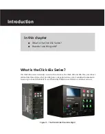
Reviews: