background image

MANUAL

Draw Wire Sensor

SERIES SX300

Summary of Contents for SX300 Series

Page 1: ...MANUAL Draw Wire Sensor SERIES SX300 ...

Page 2: ...al of WayCon Positionsmesstechnik GmbH SUBJECT TO CHANGE WayCon Positionsmesstechnik GmbH reserves the right to change this document without notice VERSION NUMBER 4 0 STAND 08 07 2020 CONTACT WayCon Positionsmesstechnik GmbH Mehlbeerenstraße 4 82024 Taufkirchen Phone 49 89 679713 0 Fax 49 89 679713 250 Email sales waycon de Internet www waycon biz WayCon Positionsmesstechnik GmbH ...

Page 3: ...es and screws 12 5 1 3 Mounting position and accessibility 12 5 1 4 Applying extra weight to the transducer 12 5 2 Fixation of the wire at the piston 13 5 3 Mounting procedure instruction 13 5 8 Mounting of a rotary transducer with shaft 15 5 9 Mounting of the Series M58 16 6 MAINTENACE AND SERVICE 17 6 1 Maintenance Plan 17 6 2 Elimination of failures during operation 17 6 3 Encoder change 18 6 4...

Page 4: ...nder head By givingfeedbacksignalstoamachinecontrolunit itispossibletocontrolthepositionofacylinder toprogramspecificmovements or to manage synchronous movements of several cylinders Due to its small overall size its short assembly time and its possible customisation this sensor technology is a cost effective and flexible solution for a wide range of industrial applications Typical Applications hy...

Page 5: ...ttention Do not varnish moving parts encoder shaft coupling Output signal Link to the encoder SSI 8 5883 6624 G322 CANopen 8 5888 6622 2123 Profibus DP 8 5888 6632 3113 EtherCAT 8 5888 66B2 B212 Profinet 8 5888 66C2 C212 4 20 mA M58 SC W 10 420A SR12 Linearity 0 05 independent of the measurement range Resolution scalable via Software no yes no Resolution standard Pulses mm Bit 14 4 13 14 4 13 12 S...

Page 6: ...STEPS OF 90 Ra0 8 Ra0 8 encoder cap for SSI encoder X 71 mm for Profibus encoder X 98 mm for EtherCAT encoder X 98 mm for CANopen encoder X 98 mm 106 5 146 222 99 Ø X SCREWED SEALING PLUG 30 Ø 245 Ø 18 12 BORE Ø 249 229 189 5 28 Ø 130 f7 Ø 279 Ø 1 5 x 45 1 5 x 45 35 115 150 196 5 MINIMESS 1620 2103 01 18 00 M10 EYE BOLT DIN 580 22 65 157 3 TECHNICAL DATA ...

Page 7: ...3 42 x 3 53 NBR AND BACK UP RING Ra0 8 Ra0 8 encoder cap for SSI encoder X 71 mm for Profibus encoder X 98 mm for EtherCAT encoder X 98 mm for CANopen encoder X 98 mm 106 5 146 222 99 Ø X SCREWED SEALING PLUG 30 Ø 245 Ø 18 12 BORE 249 229 189 5 28 Ø 130 f7 Ø 279 Ø 1 5 x 45 1 5 x 45 35 115 150 196 5 MINIMESS 1620 2103 01 18 00 M10 EYE BOLT DIN 580 22 65 157 3 TECHNICAL DATA ...

Page 8: ... 8 3 TECHNICAL DATA Flange type F1 rod sealing for 4 20 mA 99 31 100 35 48 5 123 5 345 5 Ø Ø ...

Page 9: ... 9 Flange type F2 piston sealing for 4 20 mA 99 31 100 35 48 5 123 5 345 5 Ø Ø 3 TECHNICAL DATA ...

Page 10: ...are interchangeable 4 1 3 Initial testing of encoder Connect the encoder in a de energized state only Make sure that the operating voltage for the encoder is correct and the max permissible output current is not exceeded see technical data The operating voltage for encoder and succeeding device must be turned on and off together For setting up functions refer to the technical data chapter 4 1 4 In...

Page 11: ... 2 3 Double acting cylinders Do not use the SX300 in combination with a double acting cylinder Note The responsibility of performing a regular maintenance service rests with the operator of the facility WayCon will not carry out any maintenance service neither in the course of new installation nor in the course of warranty or guarantee services 4 3 Instructions for safe handling According to the w...

Page 12: ...hould be put with low impedance on both face and back of the encoder and the transmission end In case of earth loop problems the protection earth of the encoder side has to be removed On this occasion the encoder should be placed electrically isolated opposite the actuation The encoder lines should run separately from cables with high noise levels Consumers with high disturbance levels e g frequen...

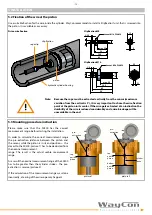
Page 13: ... M 8 13 Clipfixation M14 hex nut M14 DIN439 11 Ø 4 50 45 max 28 M 14 3 1 22 36 5 5 INSTALLATION 5 3 Mounting procedure instruction Please make sure that the SX300 has the correct measurement range before starting the installation In order to calculate the correct measurement range the pre extraction distance between the piston and the sensor while the piston is in its end position the closest to t...

Page 14: ... the rope through the hole and hang the rope clip in the clip fixation Finally close the rope clip again Note Do not let the draw wire snap If the draw wire retracts freely into the sensor it can cause injury and damage the device Take care when unhooking and retracting the draw wire into the sensor Avoid leading the draw wire over edges or corners Move the transducer toward the cylinder head and ...

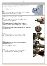
Page 15: ... spacer sleeves 8x14x35 Step 4 Secure the coupling to the SX300 shaft by tightening the two setscrews Use a torque of 2 up to 2 5 Nm Attention Do not apply excessive force Step 5 Fix the protection cap with three M8x90 for Series Encoder M58 screws Make sure that the opening leaves the connector output free 15 5 INSTALLATION Screw the nuts onto the stud bolts at the bottom of the flange Tighten th...

Page 16: ...nal would be 5 07 mA As the cylinder stroke is 9 5 m the output signal at the pistons bottom position would be 15 2 mA In this example the wire rope would be totally extracted for 10 5 m For this reason a SX300 with a nominal measurement range of 10 m would not be sufficient although the cylinder stroke is only 9 5 m Note Please use for teaching of the rotary transducer the manual of the Series M5...

Page 17: ... signal Encoder stator coupling broken or loose Check encoder stator coupling change if necessary Note We highly recommend to carry out all repairs by transducer specific skilled and trained fitters only Proper maintenance includes the regular check of the operating medium check for leakages check of encoder fixation and the output signal control 6 1 Maintenance Plan This maintenance plan gives yo...

Page 18: ...or the encoder fixation screws The connector orientation can be chosen in 90 degree steps Note Please refer to the encoder guidelines supplied by the encoder manufacturer and delivered with the encoder transducer Important Note The procedures that are described in following chapters including disassembly and assembly of the transducer may only be carried out by specially trained persons Special kn...

Page 19: ...th holding back the center spring hook to avoid a uncontrollable spring roll off Note Only by transducer specific trained persons The stored energy of the spring may lead to injuries when being mishandled Sufficient energy is stored into the spring even if the spring set is turned to zero torque Remove encoder see chapter 6 2 Loosen 2 screws of the encoder adapter and remove it in axial direction ...

Page 20: ...te Only by transducer specific trained persons Do not bend or apply radial force to the rotation shaft The rotation shaft and seal could be damaged Beforeassemblingthetransducerchangerotatingshaftseals 2pcs andbearings 2 pcs installed in the main housing and main housing cap Check rotation shaft against axial run out wear and abrasion Check surface against notches and scratches Change rotation sha...

Page 21: ... Push the capstan into the housing as far as the cylinder bolt will fit into the slot of the capstan Finally pull the wire straight Note Be aware of the narrow gap between housing and capstan Do not jam wire rope between main housing and capstan Push the rotation shaft until it reaches the end stop Fix the clamp ring of the wire capstan use screw locking device Clean the shaft from screw locking d...

Page 22: ...being mishandled Avoid guiding the rope over edges or corners Turn slowly clockwise Let the wire rope run into the transducer and turn the spring set at same time two persons are necessary If the wire rope is fully drawn into the transducer apply 3 pre load turns to the spring set Fix the spring set with screws use screw locking device and apply lacquer Check measurement range and rope forces Note...

Page 23: ... filling pipe and mount the new rings Note Take care that you do not mix the assembly sequence Please refer to the pictures o rings are black coloured back up rings are brown coloured Assembly Installation in reverse order Note Take care not to damage any o rings and back up rings Always grease the rings and sealing surfaces While pushing in the filling pipe into the housing gently turn the pipe A...

Page 24: ...l the protection cap and flood the encoder 6 6 1 Storage When storing the transducer less than 1 month the oil film built up in the course of the functional test at WayCon will be sufficient protection The storage room must be dry and free from vapours or etching agents If the transducer shall be stored for a longer period e g up to 6 months all uncoated parts must be provided with an external pre...

Page 25: ...ion qty no description qty 1 encoder 1 6 wire fixation unit M8 A2 1 2 mating connector cable 1 7 counternut DIN 934 M8 A2 1 3 encoder protection cap includes no 5 1 8 encoder adaptor 1 4 encoder screw M3x8 2 9 encoder adaptor screws DIN913 M3x4 A2 2 5 encoder cap screw 3 4 6 7 5 3 4 1 8 9 not shown 22 20 21 23 19 18 17 16 12 15 14 13 12 11 10 7 SPARE PARTS 7 3 Exploded view flange assembly 2 ...

Page 26: ...1 16 screw sealing set 6 pcs 1 23 nut DIN934 M6 1 7 4 Exploded view transducer housing 7 4 1 Part list transducer housing SX300 15 F2 transducer housing no description qty no description qty 24 spring housing assembly includes 3 springs and no 25 SX300 FED 1 32 cylinder bolt DIN6325 3x18 1 25 main housing cap 1 33 wire capstan 1 26 rotation shaft 1 34 clamp ring 1 27 housing nut DIN934 M16 12 16 3...

Page 27: ...ter manometer oil filling unit measuring tape Manufacturer Waycon Positionsmesstechnik GmbH Mehlbeerenstr 4 82024 Taufkirchen Germany Marking Article No SX300 10 M420AT F2 Serial No 17556725 Year of manufacture 2017 Operating pressure 300 bar 30 MPa Testing pressure 400 bar 40 MPa Nominal measurement range 10 m Testing range 10 30 m Material insp certificate 3 1 B as per EN10204 DIN 50049 Test per...

Reviews: