

This Installation document is available at no charge from:
- Your local Wayne Dalton Sales Center, or
- Online at
www.Wayne-Dalton.com
, or
- By mailing to: Wayne Dalton, a division of Overhead Door Corporation, P.O. Box
67, Mt. Hope, OH., 44660
©Copyright 2017
REV13_06/02/2017
Part Number
T a b l e O f C o n t e n t s
344597
PLEASE DO NOT RETURN THIS PRODUCT
TO THE STORE
If you need assistance, please call 1-866-
569-3799 (press Option 1) and follow the
prompts to contact a customer service
representative. They will be happy to handle
any questions that you may have.
Pre-Installation 2
Important Safety Instructions
2
Removing an Existing Door and Preparing the Opening
2
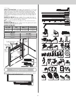
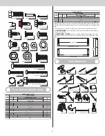
Package Contents
3
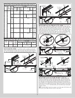
Door Section Identification
4
Tools Required
4
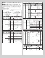
Breakdown Of Parts
5
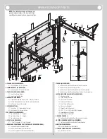
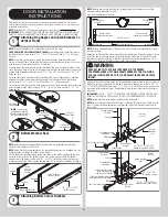
Door Installation Instructions
6
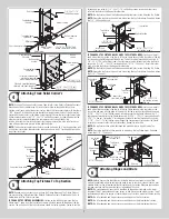
Counterbalance Installation Instructions
13
Optional Installation
16
Trolley Arm Hookup
16
Inside Lock
16
Pull Down Rope
16
Maintenance 17
Cleaning Your Garage Door
17
Painting Your Garage Door
17
Maintaining The Finish On Your Garage Door
17
Operation And Maintenance
17
Warranty 19
Wayne Dalton, a division of Overhead Door Corporation
Models 8300 / 8500
E
x t E n s i o n
i
nstallation
i
nstructions
a
nd
o
wnEr
’
s
M
anual
r
EsidEntial
s
tandard
l
ift
To avoid possible injury, read and fully understand the enclosed
instructions carefully before installing and operating the garage door. Pay
close attention to all warnings and notes. After installation is complete,
fasten this manual near garage door for easy reference.
IMPORTANT NOTICES!


