

325001
Use this insert in conjunction with your door’s Installation Instructions and Owner’s Manual.
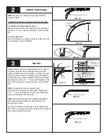
(2) #12 X 1/2”
PHILLIPS HEAD SCREWS
OPPOSITE SIDE OF OPERATOR
BRACKET
FIG. 1.3
NOTE:
Operator bracket must be mounted and secured prior to
installing top section.
IMPORTANT!
WHEN CONNECTING A TROLLEY TYPE GARAGE
DOOR OPENER TO THIS DOOR, A WAYNE-DALTON OPENER /
TROLLEY BRACKET MUST BE SECURELY ATTACHED TO THE TOP
SECTION OF THE DOOR, ALONG WITH ANY U-BARS PROVIDED
WITH THE DOOR. THE INSTALLATION OF THE OPENER MUST BE
ACCORDING TO MANUFACTURER’S INSTRUCTIONS AND FORCE
SETTINGS MUST BE ADJUSTED PROPERLY.
Prior to installing top section, locate the center of the top
section and seat the operator bracket on male part of top section,
align the center of both tabs of the bracket with the section’s
center line.
For retro fit applications, the operator bracket must be aligned
with an existing operator and positioned on top section so it
bridges the transition point of the section thickness, as shown in
FIG. 1.1
and
1.2
.
Install (2) #12 x 1/2” phillips head screws on the opposite side of
operator bracket, as shown in
FIG. 1.3
.
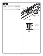
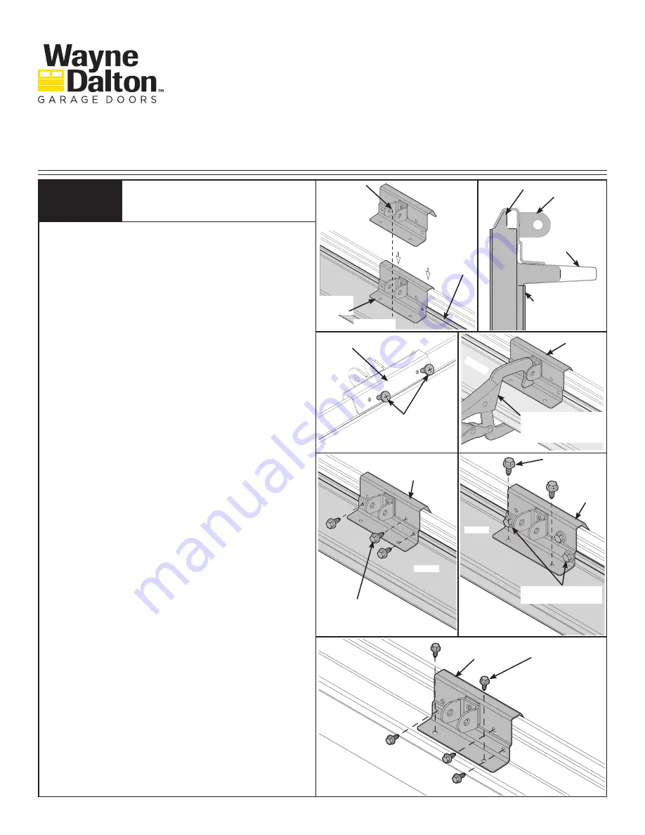
Install top section at this time. Secure u-bar (if furnished) using
1/4” - 20 x 11/16” self-drilling screws as instructed in the door
manual and then clamp operator bracket to u-bar, as shown in
FIG. 1.4
.
First attach (3) 1/4” - 14 x 5/8” self-tapping screws to the opera-
tor bracket, as shown in
FIG. 1.5
.
Then attach (2) 1/4” - 14 x 5/8” self-tapping screws to the opera-
tor bracket, as shown in
FIG. 1.6
. Remove vice clamps.
NOTE:
If you have a 9100 door, you can use two of the
1/4” - 20 x 11/16” self-drilling screw used to attach the u-bar
instead of the 1/4” - 14 x 5/8” self-tapping screw when
attaching operator bracket to u-bar, as shown in
FIG. 1.6
.
NOTE:
When attaching operator bracket to top section with u-bar,
apply additional pressure to thread the fasteners into the u-bar.
NOTE:
See
FIG. 1.7
for installing operator bracket on top section
without u-bars.
OPERATOR BRACKET
1
U-BAR
VICE CLAMP
NOTE:
NOT REQUIRED FOR
J-STRUTS.
OPERATOR BRACKET
FIG. 1.2
U-BAR
TOP SECTION
OPERATOR
BRACKET
MALE PART OF TOP SECTION
TOP SECTION
WITH OR
WITHOUT
U-BAR
ALIGN CENTER
OF BOTH TABS
WITH CENTER
LINE OF TOP
SECTION
OPERATOR
BRACKET
FIG. 1.1
OPERATOR
BRACKET
(5) TYPICAL
1/4” - 14 X 5/8”
SELF-TAPPING SCREWS
FIG. 1.7
U-BAR
(2) 1/4” - 20 X 11/16”
SELF-DRILLING SCREWS
OPERATOR
BRACKET
(2) 1/4” - 14 X 5/8”
SELF-TAPPING SCREWS
FIG. 1.6
FIG. 1.5
U-BAR
(3) 1/4” - 14 X 5/8”
SELF-TAPPING SCREWS
OPERATOR
BRACKET
REV7 05/03/2016
Trolley Arm Attachment /
Operator Bracket
Models: 9100, 9600, 5120, 5145
Installation Instructions Insert
FIG. 1.4
©
Copyright 2016 Wayne Dalton, a division of Overhead Door Corporation
Wayne Dalton, a division of Overhead
Door Corporation
P.O. Box 67, Mt. Hope, OH 44660
www.Wayne-Dalton.com


