


SPECIFICATIONS
POWER SUPPLY REQUIREMENTS
120 or 230 V, 60 Hz
MOTOR
Split Phase
HORSEPOWER
1 HP .................... (CWS100)
3/4 HP ................ (CWS75)
1/2 HP...................(CWS50)
LIQUID TEMPERATURE RANGE
40° F- 120° F
CUT IN PRESSURE
30 PSI
CUT OUT PRESSURE
50 PSI
640000-001 B 08/18
© 2018, WAYNE/Scott Fetzer Company.
CONSTRUCTION
MOTOR HOUSE
Cast Iron
SEAL PLATE
Cast Iron
DIFFUSER
Thermoplastic
IMPELLER
Thermoplastic
SHAFT
Carbon Steel
PUMP SUCTION
1-1/4 in. NPT
PUMP DISCHARGE
3/4 in. NPT
Convertible Well Jet Pump Water Systems
www.waynepumps.com
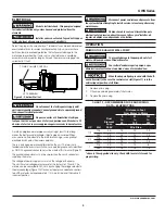
PERFORMANCE
Model
HP PSI 0 ft
10 ft 20 ft 30 ft 40 ft 50 ft 60 ft 70 ft 80ft 90 ft
CWS100
1
30
1056
948
846
750
642
516
384
294
234
180
40
840
750
642
528
384
294
234
180
126
72
50
588
444
330
264
234
180
126
72
-
-
CWS75
3/4
30
990
906
774
630
510
408
306
246
186
54
40
780
630
510
408
306
246
186
114
54
-
50
462
330
270
216
156
90
-
-
-
-
CWS50
1/2
30
900
780
690
570
456
348
270
180
90
-
40
660
570
450
348
270
180
90
-
-
-
50
408
300
210
150
60
-
-
-
-
-
Intended for Indoor Use Only
Please read and save these instructions. Read carefully before attempting to assemble, install,
operate or maintain the product described. Protect yourself and others by observing all safety
information. Failure to comply with instructions could result in personal injury and/or property
damage! Retain instructions for future reference.
Operating Instructions and Parts Manual
CWS Series
* Refer to Page 13 for Jet Assembly Part Numbers


