80
-e.DOC / K-Actros 29.01.2004
Page 1
We are glad that you have decided on one of the precious WEDICO
truck models! For the manufacture of individual parts WEDICO uses
durable materials of high quality - rarely to find in these days. This
guarantees durability and enjoyment of your model for years to come.
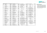
If you should ever require replacement parts, please get in touch
with your dealer or directly with WEDICO. For order purpose it is
important using not only those EDP-numbers mentioned within the
general parts list (see last page of this instruction) but also indicating
the necessary details concerning colour, quantity and exact term of the
spares required. You may be assured that WEDICO will supply the
replacement part as quick as possible.
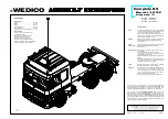
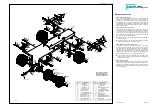
qÉÅÜåáÅ~ä=Ç~í~W=
Truck tractor:
Length ............................................... 458 mm
Width ................................................. 190 mm
Height ................................................ 226 mm
Track (tread) front.............................. 140 mm
Track (tread) rear............................... 116 mm
Weight with motor drive and NiCads..... 3.5 kg
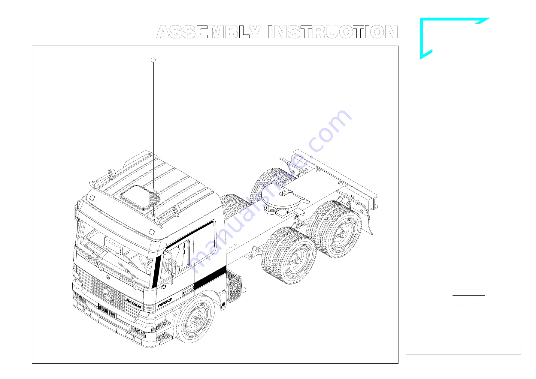
Superstructure:
Components of die cast aluminium
and aluminium sheet,
stainless steel threaded connectors
and bending wire components,
high impact plastic components.
Cab tiltable. The roof -together with the
top device of the rear panel- is detachable.
Model is prepared for R/C-installation.
®
WEDICO
Art.-No. 80 white
Art.-No. 81 blue
Art.-No. 82 yellow
`çãéäÉíÉ=háí=
jÉêÅÉÇÉë==
^`qolp
=
aêáîáåÖ=ãçÇÉä==`=
B-80-01
B-80-02
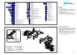
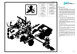
Technical data
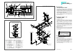
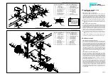
Drive
Motor: WEDICO-Bühler electric motor, rated voltage
12 volts, 7-segment collector. Idling speed 6000 rpm.
Torque 5 Ncm (approx. 500 pcm) at 4000 rpm.
Power drawn under load at max. torque approx. 3 A.
Idling power consumption with connected gearing
and one differential approx. 0.5 A.
Gearbox
Standard single speed 2-stage spur gearbox with
self-lubricating gearwheels. Reinforced housing.
Gear ratio 5.6 : 1.
Power
transmission
Stainless steel drive shafts with ball joints between
gearbox and differential. Differential gear.
Gear ratio 2 : 1.
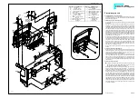
Superstructure
Frame made of aluminium section, 2 mm thick; tor-
sion resistant.
Rear bumper made of section 2 mm thick.
3-part (rear) to 4-part (front) stainless steel leaf
spring packages on all axles.
Soft rubber tires with reproduction of original tread
pattern.
Fastening components made of stainless steel. All
body parts are made from aluminium sheet and
aluminium die cast 1.5 to 2 mm thick.
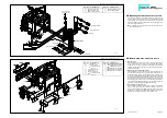
Finish
Extremely hard epoxy powder coating. Excellent
base when repainting for special purposes.
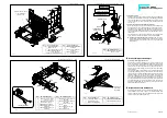
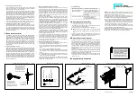
Assembly
During assembly it is advisable following the se-
quence given by these instructions. Observe the
notes explaining the various steps in assembly and
use only those parts which are provided; this will
insure a correct result of assembly.
WEDICO system kits are known for their exact fit.
© 2001 by WEDICO, P.O. Box 20 04 18, D - 42 204 Wuppertal, Germany.
We can assume no liability for technical or typographical errors.
We reserve the right to incorporate technical modifications.
Duplication and reproduction only with our express consent.


