background image

Your new tool has been engineered and manufactured to WEN’s highest standards for dependability, ease 

of operation, and operator safety. When properly cared for, this product will supply you years of rugged, 

trouble-free performance. Pay close attention to the rules for safe operation, warnings, and cautions. If 

you use your tool properly and for its intended purpose, you will enjoy years of safe, reliable service.

IMPORTANT:

NEED HELP? CONTACT US!

Have product questions? Need technical support? 

Please feel free to contact us at:

MODEL 65911

For replacement parts visit

800-232-1195 

(M-F 8am-5pm CST)

techsupport@wenproducts.com

WENPRODUCTS.COM

WENPRODUCTS.COM

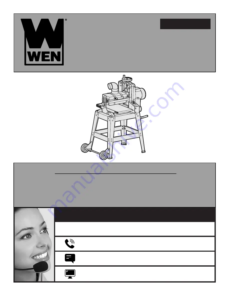
10-INCH

DRUM SANDER

Summary of Contents for 65911

Page 1: ...close attention to the rules for safe operation warnings and cautions If you use your tool properly and for its intended purpose you will enjoy years of safe reliable service IMPORTANT NEED HELP CONTACT US Have product questions Need technical support Please feel free to contact us at MODEL 65911 For replacement parts visit 800 232 1195 M F 8am 5pm CST techsupport wenproducts com WENPRODUCTS COM W...

Page 2: ... Conveyor Feed Speed 0 to 10 FPM Maximum Workpiece Width 9 7 8 250mm Minimum Workpiece Width 3 4 19mm Maximum Workpiece Height 3 1 8 80mm Minimum Workpiece Height 3 16 5mm Minimum Workpiece Length 4 3 4 120mm Sandpaper Width 3 1 4 82mm Sandpaper Length 62 1 2 1585mm Sanding Drum Size 5 1 8 x 10 1 4 132mm x 260mm Dust Port Diameter 4 101 6mm Floor to Conveyor Height 30 1 4 Assembled Dimension 28 3 ...

Page 3: ...meant to cover all possible conditions and situations that may occur WEN reserves the right to change this product and specifications at any time without prior notice Keep this manual available to all users during the entire life of the tool and review it frequently to maximize safety for both yourself and others WARNING Indicates danger warning or caution The safety symbols and the explanations w...

Page 4: ...m heat oil sharp edges or moving parts Damaged or entangled cords increase the risk of electric shock 4 If operating a power tool in a damp location is unavoidable use a ground fault circuit interrupter GFCI protected supply Use of a GFCI reduces the risk of electric shock PERSONAL SAFETY 1 Stay alert Watch what you are doing and use common sense when operating a power tool Do not use a power tool...

Page 5: ...ol serviced by a qualified repair person using only identical replacement parts This will ensure that the safety of the power tool is maintained This product and some dust created by power sanding sawing grinding drilling and other construction activities may contain chemicals including lead known to the State of California to cause cancer birth defects or other reproductive harm Wash hands after ...

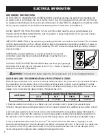
Page 6: ...GE FOR EXTENSION CORDS 25 ft 50 ft 100 ft 150 ft 10 5A 16 gauge 16 gauge 14 gauge 12 gauge ELECTRICAL INFORMATION CHECK with a licensed electrician or service personnel if you do not completely understand the grounding instructions or whether the tool is properly grounded USE ONLY THREE WIRE EXTENSION CORDS that have three pronged plugs and outlets that accept the tool s plug as shown in Fig 1 Rep...

Page 7: ...erious personal injury and machine damage 6 WORKPIECE DIMENSIONS To maintain stable operation do not sand materials shorter than 4 3 4 inches 120mm or narrower than 3 4 inches 19mm 7 WORKPIECE QUANTITY Never sand two or more workpieces side by side No two workpieces are exactly the same thickness One of them may be shot out from the sander at high speed and cause injury 8 WORKPEICE SUPPORT Support...

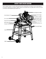
Page 8: ...rns please contact our Customer Service at 800 232 1195 M F 8 5 CST or email us at techsupport wenproducts com Height Adjustment Wheel Circuit Breaker Sanding Drum Motor Cutting Depth Pointer Conveyer Motor ON OFF Switch Feed Rate Dial Carrying Handles Dust Collection Port Drum Cover Height Lock Knob Belt Tracking Adjustment Conveyor Belt Stand Wheels 8 ...

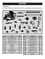
Page 9: ...4 2 4 Short Bottom Brace 20 1 4 2 5 Long Bottom Brace 23 1 8 2 6 Legs 4 7 Feet Pads 4 8 Wheel Brackets 2 9 Wheels 2 10 Wheel Axle 1 11 Lifting Handle Assembly 2 12 Height Adjustment Wheel 1 13 Dust Port 1 NO HARDWARE QTY S1 Carriage Bolts M8 1 25 x 12 32 S2 Lock Nuts M8 1 25 36 S3 Hex Bolts M8 1 25 x 16 4 S4 Cotter Pins 4 x 20mm 2 S5 Flat Head Screws M6 1 x 10 4 S6 Lock Nuts M6 1 4 S7 Hex Bolts M1...

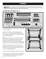
Page 10: ...per support mounting holes the other with wheel mounting holes on the bottom of each leg Make sure that the short braces connect legs of matching styles 3 Attach the 4 bottom braces to the lower brace mounting holes of the 4 legs with the remaining 16 M8 1 25 x 12 carriage bolts and 16 M8 1 25 lock nuts Hand tighten all fasteners 4 Slide the 4 feet pads onto the bottom of the 4 legs 5 Turn the sta...

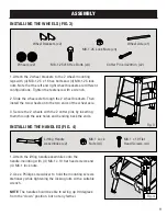
Page 11: ...ting them through the axle holes and bending back the ends INSTALLING THE HANDLES FIG 4 1 Attach the lifting handle assemblies onto the handle mounting with 4 M6 1 x 10 flat head screws and 4 M6 1 lock nuts 2 Use a Phillips screwdriver to hold the mounting screws stationary while tightening the locking nuts with a suitable wrench NOTE The handle should be able to swing up 90 degrees from the down ...

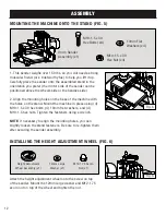
Page 12: ...ng 4 M10 1 5 x 30 hex bolts 4 10mm flat washers and 4 M10 1 5 hex nuts Tighten the fasteners using a wrench NOTE If necessary to align the mounting holes you can slightly loosen the stand fasteners Be sure to re tighten them after securing the sander assembly INSTALLING THE HEIGHT ADJUSTMENT WHEEL FIG 6 Attach the height adjustment wheel onto the screw on top of the sander Mount the 12mm large was...

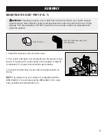
Page 13: ...tion system 1 Install the dust port onto the drum cover 2 Fit a 4 inch dust hose not included over the dust port and secure it in place with a hose clamp not included A tight fit is necessary for proper dust collection performance 3 Connect the dust hose to your dust collection system of choice NOTE The dust port on your sander is compatible with the WEN 28200 10 ft dust hose and the WEN 28221 20 ...

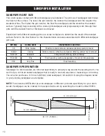
Page 14: ... sandpaper and progressively work through finer grits until the desired finish or thickness is achieved Experiment with different sanding grits on a scrap workpiece to determine the result of the sanded surface Refer to the chart below for the characteristics and uses associated with different sandpaper girt sizes SANDPAPER PREPARATION Sandpaper for drum sanders are trimmed specifically to properl...

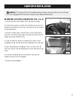
Page 15: ...ift up the cover to expose the sanding drum 3 Roll the sanding drum until the slot on the right side of the drum is on top Reach under the right lip of the drum to locate the spring clamp Fig 8 4 Push forward the clamp to release the tension on the sandpaper Slide out the end of the sandpaper from the slot 5 Start unwinding the sandpaper from the drum Fig 9 until you come to the clamping device on...

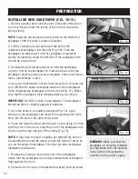
Page 16: ...o the drum Fig 11 Make sure that the sandpaper strip remains tight as you wrap it IMPORTANT DO NOT overlap the sandpaper The sandpaper should be flush or slightly gapped in between 5 Once the drum is completely wrapped Fig 12 keep tension on the sandpaper and insert the remaining end of the strip into the slot on the right of the drum 6 Press the clamp forward until the slot on the clamp is in lin...

Page 17: ...w for materials that you should avoid or take extra care with FOREIGN OBJECTS Foreign objects such as nails staples dirt rocks etc are often embedded in wood The objects may cause kickback that can hit the operator and damage the machine Remove those foreign objects before operation LARGE OR LOOSE KNOTS Choose workpieces that do not have large or loose knots Large knots may cause kickback and dama...

Page 18: ...pth of cut can be adjusted by rotating the height adjustment wheel Fig 14 2 Rotating the handwheel 1 4 turn adjusts the depth of cut by 1 32 inch Generally a 1 4 turn of the handwheel 1 2 3 Convex Concave Fig 14 18 1 32 depth of cut per pass is acceptable for coarser grits or softer woods A 1 8 turn of the handwheel 1 64 depth of cut is recommended for finer grits or harder woods TO ADJUST THE DEP...

Page 19: ...nd lungs could result from using this machine without proper protective gear Always wear safety glasses and a respirator when operating this machine 1 Fig 15 19 clockwise increases the feed rate and rotating it clockwise decreases the feed rate For the best result test on a scrap piece of wood of similar material and adjust the feed rate accordingly MOTOR OVERLOAD PROTECTOR Your drum sander is equ...

Page 20: ...he belt s movement Hold the workpiece on the conveyor and carefully ease it into the sander Be careful not to get your hand or any body parts close to the sanding drum 8 Once the sanding drum has control of the workpiece step to the side of the outfeed conveyor belt and support of the workpiece as it leaves the sanding drum Do not stand in line with the sanding path NOTE Do not apply upward or dow...

Page 21: ...tension should be properly adjusted to ensure safe operation and protect the belt from damage The belt tension can be adjusted by rotating the tensioning screws on both sides of the conveyor table To adjust the belt tension 1 Turn off and disconnect the machine from the power source 2 Release the belt tension equally on both sides of the table by holding the hex nuts Fig 16 1 in place while rotati...

Page 22: ...parent immediately Make small corrections of approximately 1 4 turn increments to the tensioning knob and evaluate the results Re adjust as necessary until the belt is tracking properly ADJUSTING TENSION SCREWS FIG 17 18 The six height adjustment tension screws on the height adjustment wheel side of the sander apply pressure to the sliding mechanism of the sanding head The tightness of the screws ...

Page 23: ...that produces a thicker sanding result Slide a metal shim not included between conveyor table and the frame to slightly elevate the conveyor table to reduce the sanding thickness on that side 6 Tighten the cap screws to secure the conveyor table 7 Repeat steps 2 to 6 as necessary until the alignment between the conveyor belt and drum is within 0 05 difference ADJUSTING PRESSURE ROLLER FIG 21 22 Th...

Page 24: ...been properly adjusted Close the drum cover and replace the washer and cap screw ADJUSTING THE STOP SCREW FIG 23 The height adjustment stop controlled by the protrusion of the Phillips head screw through the bottom of the frame prevents the sanding drum from contacting the conveyor belt If necessary re adjust the height adjustment stop screw as follow 1 Turn off and disconnect the machine from the...

Page 25: ...nce operations WARNING Use caution when performing maintenance on the drum sander Do not wear long sleeve shirts neckties or jewelry Make sure to tie back long hair WARNING Do not use solvents to clean plastic parts Do not at any time let brake fluids gasoline petroleum based products penetrating oils etc come in contact with plastic parts Chemicals can damage weaken or destroy plastic which may r...

Page 26: ...e the drum cover and lock it with the washer and cap screw LUBRICATION FIG 24 Periodically lubricate exposed moving parts the lead screw Fig 24 1 and sanding head slides Fig 24 2 Clean sawdust from the height adjustment leadscrew and sanding head slides Apply a small amount of dry lubricant such as graphite onto the surfaces Do not use oil or grease as lubricants as they tend to attract and hold s...

Page 27: ... knob Fig 25 1 and flat washer from the side support frame Fig 25 2 Then remove the hex bolts spaces and washers Fig 25 3 from the bottom of the side support frame Keep all the removed fasteners in the same configuration to be reinstalled later 4 Remove the side support frame from the sander body 5 Unscrew and remove the two cap screws and flat washers Fig 26 1 from the conveyor table 6 Hold the b...

Page 28: ...y installed 1 Inspect and tighten replace fasteners 2 Bolt machine on stable stand set on flat ground 3 Fix replace fan cover or fan 4 Contact customer service at 1 800 232 1195 for assistance 5 Contact customer service at 1 800 232 1195 for assistance 6 Replace re install sandpaper Sandpaper clogs quickly 1 Depth of cut too much 2 Feed rate too slow 3 Sandpaper grit too fine 4 Workpiece has high ...

Page 29: ...crew and nut clogged with sawdust 3 Height adjustment tension screws are too tight 1 Loosen the height lock knob 2 Clean and lubricate the leadscrew and nut page 22 3 Properly adjust the height adjustment tension screws page 22 Sandpaper strip becomes loose or comes off sanding drum 1 Sandpaper strip not properly wrapped onto drum 2 Sandpaper strip not cut to the correct dimensions 3 x 62 5 3 Slac...

Page 30: ...ut M6 1 4 12 65910 012 Short Bottom Brace 2 13 65910 013 Front Short Top Brace 1 14 65910 014 Left Long Top Brace 1 15 65910 015 Long Bottom Brace 2 16 65910 016 Right Long Top Brace 1 NO PART NO DESCRIPTION QTY 17 65910 017 Lock Nut M8 1 25 36 18 65911 018 Left Rear Stand Leg 1 19 65910 019 Carriage Bolt M8 1 25 x 12 32 20 65910 020 Left Wheel Mounting Bracket 1 21 65910 021 Wheel 5 2 22 65910 02...

Page 31: ...ON QTY 131 65910 131 Switch Housing Bracket 1 132 65910 132 Terminal Block 4P 1 133 65910 133 Switch Housing Plate 1 134 65910 134 Transformer Omron Hf 7A 24 120V 1 135 65910 135 Phlp Hd Scr M4 0 7 x 10 2 136 65910 136 Hex Bolt M8 1 25 x 16 4 137 65910 137 Insulation Plate 1 138 65910 138 Strain Relief 1 2 Snap In 3 139 65910 139 Power Cord 14G 3C 10 42870 1 140 65910 140 Conveyor Motor 24Vdc 1 14...

Page 32: ...284 285 278 279 226 226 268 280 282 235 236 281 5 281 3 281 281 1 281 2 281 6 281 4 226 268 280 227 261 263 205 289 288 240 260 239 259 233 236 255 256 257 258 249 250 252 253 251 254 233 234 235 215 216 217 290 226 205 237 229 230 232 224 225 223 222 221 243 244 245 246 247 226 268 269 248 220 219 218 214 213 212 211 210 209 208 207 206 205 204 203 201 MAIN 32 ...

Page 33: ...46 Lock Nut M4 0 7 4 247 65910 247 Pressure Roller Bushing 4 248 65910 248 Pressure Roller 2 249 65910 249 Acorn Nut M12 1 75 1 No Part No Description Qty 250 65910 250 Flat Washer 12mm 1 251 65910 251 Elevation Rotation Label 1 252 65910 252 Handwheel Assembly 1 253 65910 253 Elevation Leadscrew 1 254 65910 254 Key 5 x 5 x 16 4 255 65910 255 Hex Bolt M5 0 8 x 16 1 256 65910 256 Shaft End Cap 23 2...

Page 34: ...to be sent to WEN before the replacements can be shipped out Upon the confirmation of a WEN representative your product may qualify for repairs and service work When re turning a product for warranty service the shipping charges must be prepaid by the purchaser The product must be shipped in its original container or an equivalent properly packed to withstand the hazards of shipment The product mu...

Page 35: ...35 NOTES ...

Page 36: ...THANKS FOR REMEMBERING ...

Reviews: