background image

Page 1

WESMAR

INSTALLATION AND OPERATION

WESMAR

HD800 SERIES SONAR

INSTALLATION & OPERATION MANUAL

WESTERN MARINE ELECTRONICS

14120 NE 200th Street, PO Box 7201

Woodinville, WA 98072-4001 USA

Telephone: (425) 481-2296  Fax: (425) 486-0909

www.wesmar.com

Last Revision: November 2004

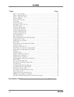
Summary of Contents for HD800/110-10

Page 1: ...ATION WESMAR HD800 SERIES SONAR INSTALLATION OPERATION MANUAL WESTERN MARINE ELECTRONICS 14120 NE 200th Street PO Box 7201 Woodinville WA 98072 4001 USA Telephone 425 481 2296 Fax 425 486 0909 www wes...

Page 2: ...ing this equipment for you The Model HD800 includes the greatest number of features ever assembled in a sonar system with multiple controls for every sonar application An historic new advancement in s...

Page 3: ...0 SONAR A GAIN RANGE ADJUSTMENTS 14 6 0 PROFILE B GAIN RANGE ADJUSTMENTS 15 7 0 TILT 16 8 0 BEARING 16 9 0 CURSOR 17 10 0 SECTOR 17 11 0 TRACK VERTICAL PROFILE SWITCH 18 12 0 FUNCTION KNOB AND SELECT...

Page 4: ...TIONING THE SOUNDOME 49 5 0 LEAD SCREW HOIST MOTOR WIRING 50 6 0 JUNCTION BOX INSTALLATION 50 7 0 CONNECTING POWER TO THE HOIST CONTROL BOARD 50 8 0 SOUNDOME WIRING 51 9 0 LEAD SCREW HOIST OPERATION C...

Page 5: ...RVOIR 81 18 0 PRE OPERATION HYDRAULIC INSPECTION 81 19 0 SOUNDOME OPERATION CHECK 82 20 0 TROUBLESHOOTING 83 21 0 RESERVOIR OIL MAINTENANCE 84 22 0 BLEEDING THE HYDRAULIC SYSTEM 85 PART F ANTIFOULING...

Page 6: ...dome and Seachest 48 Top Hoist Clamp 49 Top Hoist Clamp Side View 52 Check Points for Lead Screw and Ram Hoists 54 Clearance Between Soundome and Seachest 57 Ram Hoist 58 Hydraulic Pumps 62 Hydraulic...

Page 7: ...ion I INTRODUCTION WESMAR has built over 3 decades of sonar engineering experience into the HD800 series experience that now benefits you Congratulations on investing in what we believe will soon be t...

Page 8: ...won t be returning the sonar If a system does have to be returned to WESMAR use the packing material it arrived in PLEASEREADANYTAGSTHATMAYBEATTACHED TO THE EQUIPMENT BEFORE ATTEMPTING TO INSTALL THE...

Page 9: ...ions menus the HD800 sonars provide more information about the targets you re after so you can make the kind of catches you want profitable ones The high definition sonar screen offers four times the...

Page 10: ...Page 10 WESMAR HD800...

Page 11: ...nars that are easy to operate The HD800 Series follows this tradition by having a minimum of controls In addition the HD800 series is the world s most advanced sonar The technician or operator can cus...

Page 12: ...f There is a remote possibility the settings may return to the default set tings if there is a power surge If this happens turn the sonar off wait a few seconds and turn it back on Reset your special...

Page 13: ...nel will start to spin 1 4 The console front panel lights will illuminate vis ible under low light conditions During this period the sonar performs a system test When all the functions are operational...

Page 14: ...this page Note If brightness knob is turned completely CCW the video will still come on during self test but then fade to a black screen Simply turn the brightness knob CW to the desired brightness 5...

Page 15: ...es 0 100 are displayed to the left of the screen in the box titled NEAR Note There are two sets of numbers in the Near Box The numbers to the left correspond to the profile Near Gain Control located o...

Page 16: ...the profile sector will reduce approximately 10 degrees for each toggle Pushing up on the TILT Switch increases the profile sector 8 0 BEARING 8 1 When operating in full screen sonar 360 degree scan t...

Page 17: ...oned with the BEARING Knob and in tilt with the TILT Switch 10 3 Full Screen Bottom Profile or Full Screen Sounder Selected in Menu 1 10 3 1 BOTTOM PROFILE will scan the soundbeam across the bottom Fi...

Page 18: ...ading Heading is calculated between two or more GPS updates Because bearing is a calculation the greater the distance between GPS readings the more accurate your heading will become WESMAR recommends...

Page 19: ...ate time latitude and longitude are entered at the top of the log When the log is full the last entry at the bottom will disappear To discontinue a track sequence lift up the track switch for the thir...

Page 20: ...fast long range search Select Speed One in bottom profile for high bottom resolution When changing speed the soundbeam must be in the Sonar Screentomakechangesforsonar Thesoundbeammust be in the Profi...

Page 21: ...R will reflect your change magic 12 3 PULSE Function 3 PULSE BOX highlighted left of screen Press up or down on the SELECT SWITCH to choose BOOST 100 50 25 12 6 3 or 0 of the pre programmed pulselengt...

Page 22: ...tion 4 TVG BOX highlighted left of screen TVG can be selected separately for sonar and bottom profile Press up or down on the SELECT SWITCH to select 100 through 2000 Normal TVG settings FREQUENCY MIL...

Page 23: ...riations in the TVG slope can be calibrated for your region TVG calibration allows the operator to adjust the end of the TVG slope in range When cor rectly set all operational adjustments are then mad...

Page 24: ...s the OPTIONS MENUS press down the MENU SWITCH One of four menus will appear on the screen Each time the MENU SWITCH is pressed down a new menu will appear To return back to the active sonar display p...

Page 25: ...he selections are PORT STBD FORE AFT STB PORT AFT FORE To Sector In Profile use the Tilt Switch Push down on the Tilt Switch for smaller sectors Push up on the Tilt Switch for larger sectors Make sect...

Page 26: ...individual or disperse fish select any number 1 through 10 Any fish target that marks weak in color blue green or yellow will be enhanced and not diluted from non fish targets Start with a low target...

Page 27: ...E Select the language you wish for the Display and Menu 1 11 AUDIO MUTE You can choose two types of audio outputs WhenyouselectYES thesoundofthetransmitterfiring is suppressed and not heard over the s...

Page 28: ...RDS 3 0 MENU 3 COLOR SELECTIONS 3 1 TEXT Allthewords rangerings andbordersarewhiteincolor For night viewing WESMAR recommends lowering the intensity of the white color and not the Brightness Control o...

Page 29: ...r schooling or dis persed fish off the bottom Select 16 colors for ground fish shrimp and bottom typing 3 6 A DELETE SONAR A You are able to delete or add colors By deleting colors you are raising the...

Page 30: ...cking process Menu 4 will log in the date time latitude and longitude A total of twelve entries will be listed New trackings are added to the top of the list with the oldest dropping off the bottom 5...

Page 31: ...cewaterlayermeetsthedeepercold waters where the fish are likely to be located When the temperature changes rapidly with depth thermocline it plays an important role as the food chain tends to be locat...

Page 32: ...Page 32 WESMAR HD800 Section III INSTALLATION...

Page 33: ...sole may introduce noise and lower sensitivity In general the HD800 like all other sophisticated computerequipment mustbeprotectedfromsevere temperature conditions 2 0 ACCEPTABLE POWER SOURCES All HD8...

Page 34: ...hip s cable is large enough to send the needed amount of current through the WES MAR power cable to the sonar equipment Use the chart below for reference 4 0 CONSOLE VIDEO OUTPUT The video output of t...

Page 35: ...ve the correct connector prewired 5 0 DISPLAY MONITOR VOLTAGE If your vessel does not have the correct voltage to operate the computer monitor an inverter or converter is required For example if your...

Page 36: ...e back panel of the console NOTE The connector is keyed and will align only one way If you wish to change the align ment for easier connection follow the steps in steps in 6 1 6 1 Repositioning the Co...

Page 37: ...on the lock ing ring Make sure that no wires are pinched between the two halves 6 1 7 Screw on the cable clamp flange without twisting the cable and tighten the cable clamp screws to secure the cable...

Page 38: ...om water intakes discharge lines or zinc plates welded to the hull Air bubbles and water turbulence caused by these objects during vessel movement will reduce sonar performance Avoid installing the se...

Page 39: ...c hoist is 1 meter 39 4 inches If the seachest length is not one meter you must talk to WESMAR prior to ordering the sonar 4 Paint seachest inside and out with same paint system used on the hull 5 DO...

Page 40: ...standard ram hoist is 57 2 cm 22 5 inches 3 Length of seachest for hydraulic hoist is 1 meter 39 4 inches If the seachest length is not 1 meter you talk to WESMAR prior to ordering the sonar 4 DO NOT...

Page 41: ...75 I D nominal 2 Standard length of seachest for the 10 inch soundome is 900 mm 35 4 inches If the seachest length is not 900 mm you must talk to WESMAR prior to ordering the sonar 3 Paint seachest in...

Page 42: ...pipe 15 0 I D nominal 2 Standard length of seachest for hydraulic hoist is 1 meter 39 4 inches If the seachest length is not 1 meter you must talk to WESMAR prior to ordering the sonar 3 Paint seache...

Page 43: ...e 40 steel pipe 16 876 I D nominal 2 Standard length of seachest for hydraulic hoist is 1 meter 39 4 inches If the seachest length is not 1 meter you must talk to WESMAR prior to ordering the sonar 3...

Page 44: ...rs with hydraulic hoist are HD800 160 6 M6 1000 mm HD800 110 8 M8 1000 mm HD800 60 8 M8 1000 mm HD800 110 10 M18 900 mm HD800 45 14 M18 1000 mm HD800 27 15 M18 1000 mm If the top of the seachest rises...

Page 45: ...s to minimize vibration The bottom of the seachest must be 1 cm 5 inches above the bottom of the keel 6 0FAIRING This section only applies to seachests that extend outside the hull Build a 1 meter lon...

Page 46: ...ubbles down the keel These bubbles spread widely over the bottom of the vessel and interfere with sonar performance WESMAR recommends using only the Long Stroke Hydraulic Hoist in all bulbed bow vesse...

Page 47: ...comes standard with the Ram Hoist see Part D If there is not enough overhead clearance for a Ram Hoist a special order lead screw hoist may be used To determine the minimum length of a soundome tube...

Page 48: ...snugly WARNING Screwingthetubedowntootightlycandamage the soundome and or jam nut 2 3 6 Inch Soundome The 6 inch soundome has a FWD arrow molded into the top of the soundome bell This FWD arrow must...

Page 49: ...THE SOUNDOME To determine how high or low to position the soundome within the seachest go below the boat and measure the distance between the bottom of the soundome and the end of the seachest The cor...

Page 50: ...an be reached by the soundome cable Do not extend the length of the soundome cable as it may introduce noise and shorten range performance 2 Do not install the junction box in the fish hold or cold st...

Page 51: ...20 3 cm 8 inches See Page 55 5 8 Inch Soundome Total travel distance up or down is 28 0 cm 11 inches See Page 55 5 The hoist motor is calibrated at the factory for correct travel distance but you sho...

Page 52: ...9 1 5 When performing the next steps do not let the hoist safety clamp press into the packing gland with the motor running This could damage the hoist assembly 9 1 6 Make sure wires from Terminal 2 an...

Page 53: ...aticallystoploweringbefore it reaches bottom If the safety clamp does not stop or if it is less than 1 25 cm 5 inches above the packing gland you mustrepositionthetophoistclampontheleadscrew Check the...

Page 54: ...top of the soundome and the ceiling 3 The bottom of the seachest must be 1 cm 5 inches above the bottom of the keel 4 The 6 inch soundome must extend below the keel by at least 15 cm 6 inches The 8 in...

Page 55: ...soundome Touch Terminal 27 with the blue wire labeled 27 Top Limit Switch This will power the hoist motor and raise the soundome The hoist will rise to the Up position and stop If the bottom of the so...

Page 56: ...ile down the fins of the soundome so it fits into the seachest The clearance around the soundomeshouldnotbegreaterthan1 6mm 1 16inch 2 2 Attaching Soundome Tube to Soundome Place the jam nut on the so...

Page 57: ...ed in the down position Loosen the packing gland white guide clamp safety clamp and bronze top hoist clamp Feed the soundome cable and tube through them in the same order Tighten the top hoist clamp P...

Page 58: ...After positioning the soundome tube tighten the top hoist clamp and the safety clamp Verify the soundome is 23 cm 9 inches below the keel 5 0 RAM HOIST MOTOR WIRING Route the hoist motor wires through...

Page 59: ...nsole Use the wire chart on Page 33 Route the hoist power cable through one of the small strain reliefs in the bottom of the Junction Box For DC hoist attach positive lead to Terminal 30 and negative...

Page 60: ...oist fuse on the hoist preamp board 9 1 Hoist Operation Check Procedure Tocheckhoisttravel followthesestepsbeforereturning your vessel to the water 9 1 1 Power is off to the hoist system and con sole...

Page 61: ...up against the flange Remove the blue wire labeled 27 Loosen the top hoist clamp and slide the soundome tube down enough so the hoist motor can continue up and trigger the up limit switch and stop 9...

Page 62: ...ulic motor is removed from the hoist system After installing the hoist system replace the allen screw with the plastic thumb screw 2 The plastic thumb screw is vented to air so that the hydraulicreser...

Page 63: ...Pump 3 Reservoir 4 Relief Valve adjusted to 1500 2000 PSI 5 Solenoid Valve DC or AC 6 Pilot Actuated Check Valves 7 Pressure for lowering soundome 8 Pressure for raising soundome 9 Hydraulic Ram Unbal...

Page 64: ...Page 64 WESMAR HD800 HYDRAULIC HOIST ASSEMBLY A...

Page 65: ...Page 65 WESMAR INSTALLATION AND OPERATION HYDRAULIC HOIST ASSEMBLY B...

Page 66: ...ctory to fit the following length seachest HD800 160 6 M6 1000 mm 39 37 in HD800 110 8 M8 1000 mm 39 37 in HD800 60 8 M8 1000 mm 39 37 in HD800 110 10 M18 900 mm 35 4 in HD800 45 14 M18 1000 mm 39 37...

Page 67: ...M18 The hoist rack assembly consists of four angle legs and two angle cross supports Each of the four angle legs are labeled at on end Match the same name label of the angle legs to the flange bracke...

Page 68: ...leading into the tube will damage the hydraulic ram 6 1 3 Run the soundome cable through the soun dome tube starting at the threaded end and out through the other end 6 1 4 Screw the soundome onto the...

Page 69: ...he way into the soundome tube Make sure the hydraulic hose doesnotcomeoutonthesamesideasthelimitswitches Align the three holes in the hydraulic ram end cap with the three holes at the end of the sound...

Page 70: ...ell to indicate forward 8 inch soundome AFT that points to the fin on top of the dome to indicate the stern 10 14 15 inch soundomes FWD stamped on the side of the dome to indicate forward Make a mark...

Page 71: ...IC POWER PACK INSTALLATION M6 M8 M18 The hydraulic power pack can be installed directly on the hoist or bulkhead 13 1 Hoist installation Locate the angle leg labeled pump Align the two holes on the an...

Page 72: ...elower unusedterminal post on the DC Hoist Motor Maximum current draw is 100AMP s Use 12 mm diameter wire 4 0 AWG from the ship s battery supply Wire must not be longer than 60 meters 200 feet 15 1 2...

Page 73: ...Boththetopandbottomlimitswitchesareprewired at the factory Terminal lugs 25 and 27 are prewired to the top limit switch Terminal lugs 25 and 26 are prewired to the bottom limit switch Connect termina...

Page 74: ...Page 74 WESMAR HD800 M18 HOIST CONTROL CIRCUITRY THIS PAGE LEFT INTENTIONALLY BLANK...

Page 75: ...e hoist board 15 2 1 Voltage to AC Hoist Board ConnectShip sACpowertothefollowingterminals located top right on the Hoist Board Terminal 32 AC Ground Terminal 31 AC INPUT Terminal 30 AC INPUT Use 2 4...

Page 76: ...inches above the bottom of the keel 2 When in the raised position the bottom of the soundome must be inside the seachest 3 Hoist Travel M6 500 mm 19 7 in M6LS 920 mm 36 2 in M8 500 mm 19 7 in M8LS 92...

Page 77: ...ard and Transmitter Receiver Board The second junction box has the terminal connections for the hoist travel selec tion switch and hoist limit switches 15 3 1 Hoist travel selection switch wiring M18L...

Page 78: ...Voltage Operating voltage of the power booster is prewired at thefactoryfor110VACor220VAC Checktheoperating voltagebeforeconnectingshipsACtothepowerbooster To determine the correct voltage check the v...

Page 79: ...using two terminal strips there is more room to make the connections if a bower booster is used Wiring a power booster to the one terminal strip T R board 1 Remove the red wire 4 from the terminal an...

Page 80: ...Page 80 WESMAR HD800 T R BOARD WITH ONE TERMINAL STRIP RED WIRE 4 INTERCONNECT CABLE T R BOARD WITH TWO TERMINAL STRIPS 1 2 3 4 TB2 Term 4 XMIT PWR IN 20 TB1 for power booster TB2...

Page 81: ...nted so the hydraulic reservoir can breathe which is necessary for proper operation 18 0 PRE OPERATION HYDRAULIC INSPECTION To avoid permanent damage to your hoist hydraulics follow these steps to che...

Page 82: ...n the packing gland only until it slightly weeps water A packing gland that is too tight will create excess friction on the soundome tube If the soundome tube stops before the limit switch damage to t...

Page 83: ...eoff Move the hoist motor in small steps by tapping the 12VDC wire to Terminal 2 until the motor stops driving Do not let the tube clamp press into the shock tube 19 1 8 When the hoist stops there mus...

Page 84: ...n wires to limit switches Limit switches on hoist rack not properly aligned and are not triggering when the top hoist clamp approaches 20 4 Soundome will not stay up Dirty check valves Check for leak...

Page 85: ...YDRAULIC SYSTEM The hydraulic hoists are self bleeding If air bubbles do get into the hoses they will be expelled when the hoist has been raised and lowered several times PART F ANTIFOULING PAINT WESM...

Page 86: ...Page 86 WESMAR HD800...

Page 87: ...Page 87 WESMAR INSTALLATION AND OPERATION Section IV FIELD ADJUSTMENTS CALIBRATION...

Page 88: ...0 Pulse 100 TVG Correct number for frequency Threshold 3 1 0 POSITIVE 5 VDC ADJUST CONSOLE Connect the positive lead of a Digital Volt Meter DVM to the back side of R20 see console drawing for locatio...

Page 89: ...P5 ReceiverOutput seeT P R drawingforloca tion Connect the negative lead to TP1 Receiver Ground Select the 3 Volt DC scale on the VOM The DC scale will give better results than the AC scale Adjust the...

Page 90: ...LY FREQUENCY ADJUSTMENT CONSOLE This last adjustment is to verify that the power supply in the sonar does not interfere with targets Set Sonar A for Pulse width 0 zero percent TVG 200 Near Gain 100 Fa...

Page 91: ...Page 91 WESMAR INSTALLATION AND OPERATION R20 5 TEST POINT TP3 RECEIVER OUTPUT TP TVG Y TEST POINT HD800 Console Printed Circuit Board...

Page 92: ...Page 92 WESMAR HD800 HD J BOX TRANSMIT PREAMP RECEIVER PCB T P R...

Page 93: ...easotherHD800models Section II of the HD800 installation and operationmanualappliestotheFTmodels Installation Installation of the HD800 FT system is similar to other HD800 models Section III of the HD...

Page 94: ...usted using a screwdriver Valve is located on the left side of the pump The FT hydraulic power pack does not require a flow control valve Part F Hydraulic Hoist Installation 1 Soundome Tube Length FT...

Page 95: ...tighten evenly 7 Installing the Hydraulic Ram 7 1 Remove the strain relief at the top of the hydraulic ram end cap 7 2 Run the soundome cable through the strain relief The hydraulic ram has an indenta...

Page 96: ...n the manual 13 FT Hydraulic Power Pack Installation Locate the angle leg opposite the limit switches Half way up the leg are two holes side by side Use these holes to bolt the hydraulic power pack mo...

Page 97: ...ation Hydraulic Inspection The FT hoist will travel 457mm 18 inches Make sure there is room under your boat for this travel 18 1 Down Operational Check Pro cedure Follow procedure in manual 18 2 Up Op...

Page 98: ...Page 98 WESMAR HD800 FT Hydraulic Assembly...

Page 99: ...ounting Bracket Pilot Actuated Check Valve 12V DC Solenoid Valve 12V DC Motor 24V DC Dow n Pressure Hose Solenoid Cable to J Box Down Pressure Hose 24V DC 24V DC Motor 24V DC Up Pressure Hose Solenoid...

Page 100: ...WESTERN MARINE ELECTRONICS 14120 NE 200th Street PO Box 7201 Woodinville WA 98072 4001 USA Telephone 425 481 2296 Fax 425 486 0909 Email cjones wesmar com URL www wes mar com...

Reviews: