SECTION 1 - PREPARATION FOR INSTALLATION
Tools Needed
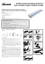
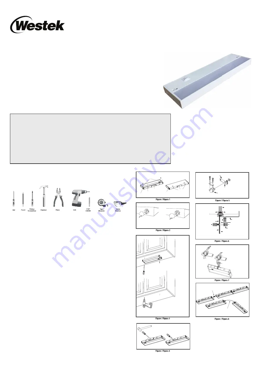
Parts of this Light Fixture
This light fi xture can be installed via direct wire connection or with the 6’ Power Cord.
Become familiar with the parts of the light fi xture. See Figure 1.
- Mounting holes go through light fi xture to make it easy to locate where to drill pilot
holes for screws or for plastic anchors (not included) if installing in drywall.
- On/Off switch
- Screw Plugs to cover screws for a clean installation.
- Rear access door can be removed to access the 3 wires with quick connector plugs.
- Knockouts are provided in rear access door and in 4” increments on back and rear of
light fi xture for convenient locating of 120V power feed for optimal fi xture placement.
(Note: only one knockout is provided on the 12” fi xture in rear access door).
- Input Panel Cover can be removed to plug in 6’ Power Cord for non direct wire
installations, the 12” linking Cord or the In-Line Connector to link fi xtures together. The
Output Panel Cover can be removed to plug in the other side of the 12” linking Cord or
the In-Line Connector to link fi xtures together. See Figure 2.
Placement of Fixture
Determine location and method for connecting 120V power for fi xture. Portable units
are attached to house wiring with the use of a plug and Power Cord. They can be easily
moved from one location to another and have limited requirements for grounding
connections. Direct Wire units are designed to be permanently mounted and are often
directly connected to the house wiring through junction boxes.
If you are not sure
about this installation consult a local licensed electrician or electrical contractor before
proceeding.
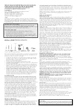
Locate Mounting Holes: Place fi xture on mounting surface and with a thin screwdriver,
pencil or scratch awl mark the spot where the screws will be located through the Mounting
Holes in the top of the fi xture. See Figure 3. Do the same for a multiple fi xture installation.
For mounting into drywall, drill 3/16” holes for the plastic wall anchors (not included). Insert
the plastic wall anchors into the proper holes and tap them into place so they are fl ush
with the surface of your drywall. For mounting into wood cabinets drill 1/16” pilot holes,
1/2” deep.
Caution: Check your cabinet thickness fi rst. Be careful not to drill through
cabinet.
Prepare fi xture for installation by turning screws provided into mounting holes in the top of
the fi xture so they protrude through the back of the about an 1/8”. This will help you line up
screws to mounting holes.
WESTEK Professional Series LED Undercabinet Lighting
Models: KERNL12W, KERNL16W, KERNL22W and KERNL30W
IMPORTANT SAFETY INSTRUCTIONS
For use with 120V, 60Hz electrical power supply only.
WARNING: TO PREVENT OVERHEATING AND ELECTRICAL SHOCK DO NOT INSTALL IN SMALL ENCLOSED SPACES. TO
PREVENT ELECTRICAL SHOCK DO NOT INSTALL IN WET LOCATIONS.
SAVE THESE INSTRUCTIONS
1. Read and understand all of these instructions before installing fi xture.
2. Keep these instructions in a safe place for future reference.
3. Only qualifi ed electricians in accordance with local codes should perform all installations.
4.
WARNING: For hard wire installation make sure electrical power supply for installation circuit is shut down at electrical
service panel before starting installation. Do not re-energize circuit until installation is fully completed. Ensure that no
bare wires are exposed outside the electrical connections.
WARNING: To prevent shock closely follow grounding directions.
FEATURES
Convertible design for plug-in & hardwiring applications
Quick and easy linking system
Dimmable Long Life LED technology
Easy Hardwiring System – Includes connectors
Aluminum housing with diffused lens
On/Off Switch
INCLUDES
KERN Series Plug-in/Direct Wire Light Fixture (12” or 16” or 22” or 30”), 6’ Power Cord,
Cable Connector, 12” Linking Cord, In-Line Connector, Mounting Hardware and (2) Screw Plugs.
CET
INSTRUCTIONS FOR INSTALLATION OF
PLUG-IN/DIRECT WIRE LIGHTING FIXTURE
Step 1 / Étape 1 / Paso 1
Locate Holes
Déterminer l’emplacement des trous
Ubique los orificios
Step 2 / Étape 2 / Paso 2
Drill Pilot Holes
Percer des trous pilotes
Perfore orificios piloto
Knockouts
Alvéoles défonçables
Agujeros ciegos
Rear access door
Trappe d’accès arrière
Puerta de acceso posterior
Mounting holes
Trous de montage
Orificios de montaje
TOP / DESSUS / PARTE SUPERIOR
BACK / DOS / PARTE POSTERIOR
On/Off switch
Interrupteur On/Off (marche/arrêt)
Interruptor On/Off (Encendido/Apagado)
Output panel
Panneau de sortie
Panel de salida
Input panel
Panneau d’entrée
Panel de entrada
Top Cover
Couvercle supérieur
Cubierta superior
Screw Plugs
Bouchons à vis
Tapones de tornillo
Screw Plugs
Bouchons à vis
Tapones de tornillo
IN PUT
OUT PUT
SORTIE
SALIDA
ENTRÉE
ENTRADA
Non-Metalic Cable (NM)
Câble non métallique (NM)
Cable no metálico (NM)
Armored Cable (BX)
Câble blindé (BX)
Cable blindado (BX)
Push-in wire connectors
Connecteurs de fil à emboîtement
Conectores de alambres insertados
AC Supply Wires
Fils d’alimentation secteur
Conductores de suministro de CA
Hot (Black) Supply Wire
Fil de phase d’alimentation (noir)
Conductor de suministro caliente (negro)
Ground (Green or Copper) Supply Wire
Fil de terre (vert ou cuivre)
Conductor de suministro de puesta a tierra (verde o cobre)
Neutral (White) Fixture Wire
Fil de luminaire neutre (blanc)
Conductor neutro (blanco) del accesorio
Neutral (White) Supply Wire
Fil d’alimentation neutre (blanc)
Conductor de suministro neutro (blanco)
Hot (Black) Fixture Wire
Fil de phase luminaire (noir)
Conductor caliente del accesorio (negro)
Armored or Non-Metallic
Cable Connector
Connecteur de câble blindé ou non métallique
Conector de cable no metálico o blindado
Ground/Yellow Fixture Wire
Fil de terre/jaune du luminaire
Conductor amarillo/de tierra del accesorio
Quick Connect Wire Connectors
Connecteurs rapides de fils
Conectores de conductores de conexión rápida
Knockout
Alvéole défonçable
Agujero ciego
Cable Connector
Connecteur de câble
Conector de cable
Rear access panel / Trappe d’accès arrière / Panel de acceso posterior
12” Linking Cord
Câble de liaison de 305 mm (12 po)
Cordón de acoplamiento de 12 pulgadas (30.5 cm)
In-Line Connector
Connecteur en ligne
Conector en línea


