Page 1
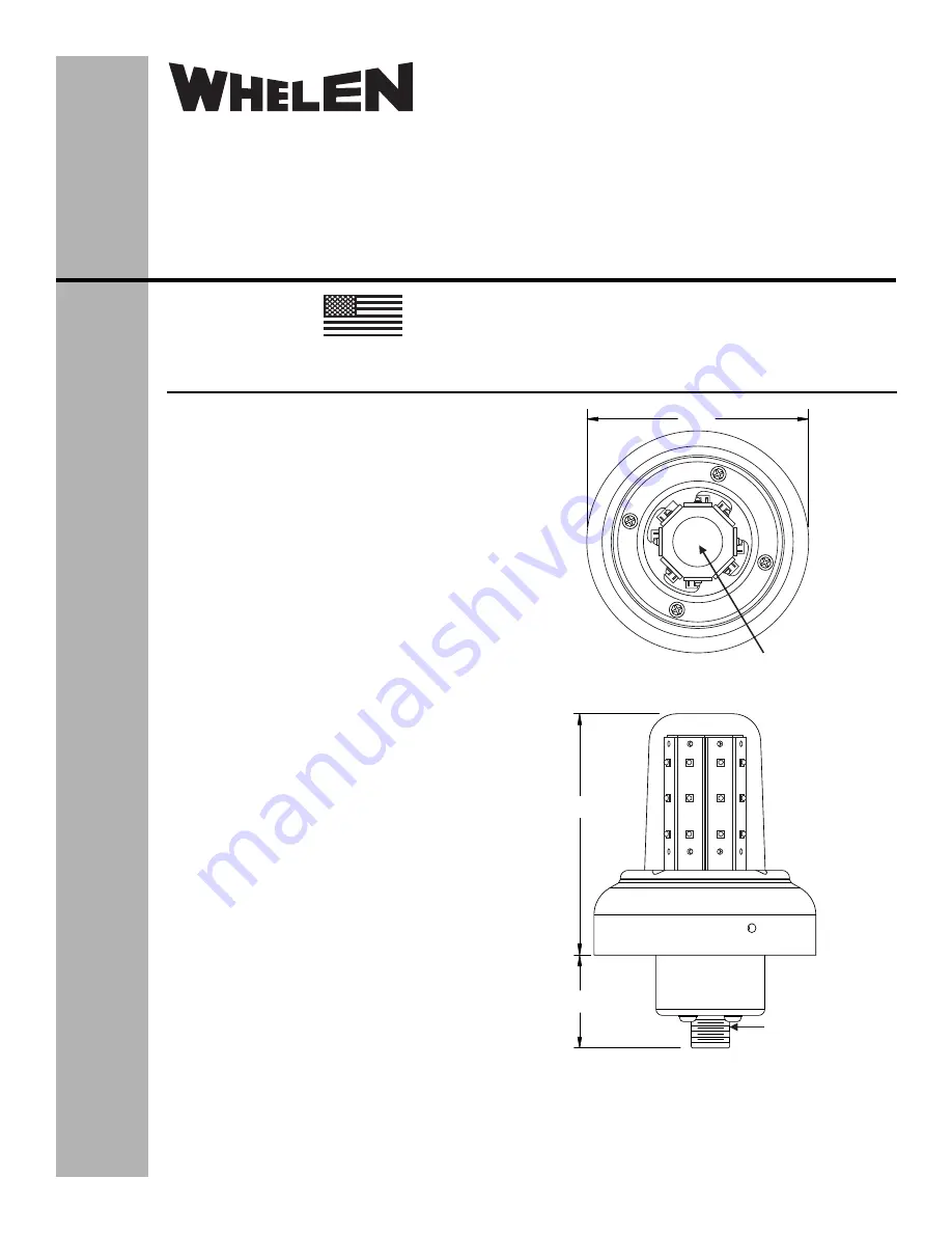
3.92
1.51
3.66
0.125 DRAIN HOLE
LOWER MOUNT ONLY
MS3102E10SL-3P
CONNECTOR
®
ENGINEERING COMPANY INC.
51 Winthrop Road
Chester, Connecticut 06412-0684
Phone: (860) 526-9504
Fax: (860) 526-2009
Internet: www.whelen.com
Sales/Service e-mail: aviation@whelen.com
Aviation
Installation Guide:
Model 71410( )-series
Model(s) 7141007, 7141017
P/N:01-0771410-07, 01-0771410-17
LED Flashing Anti-Collision
Light Assembly
©2009 Whelen Engineering Company Inc.
Form No.14355A (052914)
OPERATING INSTRUCTIONS:
Operational Voltage:
. . . . . . . . . . . 28 VDC nominal
Average Input Current:
. . . . . . . . . 0.32 Amps
Pulse Input Current:
. . . . . . . . . . . 1.4 Amps @ .3 Seconds
The Model 71410 series LED anti-collision light assembly meets
the requirements of FAR 91.205(c)(3).
CONTINUED AIRWORTHINESS:
The 71410 series LED anti-
collision light assembly is designed with 8 vertical columns
consisting of 3 white LEDs each. Should any one LED or any
vertical column fail, the unit must be repaired or replaced.
NOTE:
To reduce eye strain, use an optical filter such as dark glasses or a
blue covering dome during LED inspection. Inspect the lens and
replace if there is excessive scratching, discoloration or cracking.
INSTALLATION PROCEDURES:
The following information is to
assist in the installation of a Whelen LED anti-collision light
system.
1.
The installation procedure described in the following text will
be confined to a single light installation, but is identical for
multiple light installations.
2.
Using the “suggested mounting hole pattern” prepare the
aircraft for means to secure the LED anti-collision light
assembly. Remove any existing mounting adapters.
3.
28 VDC (+) and (-) ground leads equipped with an
appropriate sized breaker to be supplied to the LED anti-
collision light assembly system. Both leads must be
connected by an approved FAA connection. Insure that the
wire leads are clear of any obstructions and ty-wrap as
required.
4.
Install the light assembly by securing to the aircraft using
appropriate, approved hardware. Refer to page 2. CAUTION!
Do not touch the LEDs with either fingers or sharp objects.
This could soil and/or damage the LED and effect the optical
performance of the LEDs.
5.
All inverted (bottom) mounted units shall require
waterproofing of the flasher base assembly to the aircraft.
6.
Check all avionics systems for interference from this
installation.
7.
A flight check should be performed by a properly certified
pilot.
8.
Update aircraft records, complete Form 337 and obtain FAA
field approval for installation, as necessary.
TSO-C96a CLASS III
APPROVED
MADE IN THE U.S.A.
The conditions and tests required for TSO approval of this article are minimum
performance standards. It is the responsibility of those installing this article either on
or within a specific type or class of aircraft to determine that the aircraft installation
conditions are within the TSO standards. TSO articles must have separate approval
for installation in aircraft. The article may be installed only if performed under 14 CFR
part 43 or the applicable airworthiness requirements.