background image

©

Service Competence Center

Induction G0

Induction cooktop G0

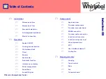
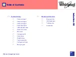
Summary of Contents for G0

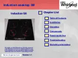
Page 1: ... Service Competence Center Induction G0 Induction cooktop G0 ...

Page 2: ... Service Competence Center Induction G0 Version 1 1 Table of Contents Installation Operation Components Repair guide line Troubleshooting Marketing information Chapter List Induction cooktop G0 ...

Page 3: ...ion Control panel lock Timer Booster Eco Booster Automatic function Indications on display Power management Demo Mode Acoustic Signal Repair guide line Housing Touch control Zone Fan Converter board Components Exploded view Overview components Overview converter board ESAM connection Overview cable connection Induction coil overview Induction coil power level Zone exploded view NTC User Interface ...

Page 4: ...akdown 7 safety points Accessories Troubleshooting Failure code type 1 Failure code type 2 Failure code type 3 Failure description LED and buzzer check Access main menu Main menu Configuration G0 Failure Show Delete Failures Test program rules Configuration Codes Wiring diagram Induction G0 ...

Page 5: ... Service Competence Center Installation Dimensions 60 cm Dimensions 77 cm Standard Installation Full integrated installation Electrical connection Induction G0 ...

Page 6: ... Service Competence Center Installation Dimensions 60cm version Information in the IFU Induction G0 Worktop thickness min 3cm ...

Page 7: ... Service Competence Center Installation Dimensions 77cm version Induction G0 Worktop thickness min 3mm ...

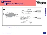
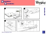
Page 8: ... Service Competence Center Installation Installation Induction G0 ...

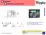
Page 9: ... Service Competence Center Installation Installation Induction G0 ...

Page 10: ...on Induction G0 G0 needs more air circulation in order to cool down the electronic parts Therefore mor free space is needed in the rear of the cooktop As well the separate cutout has to be done in the rear of the separation plate underneath the cooktop ...

Page 11: ...lation 11 5 6 0 5 Perimetral Gasket Silicon COOKTOP CUT OUT DIM mm Depth Length Width Length Width 580 Vetroceramic Cooktops Flush Installation 38 580 510 583 560 513 490 0 2 770 Vetroceramic Cooktops Flush Installation 39 770 510 773 750 513 490 0 2 Induction G0 ...

Page 12: ...ve the screw head on the outside This is important they are not reachable after installation Put in the 6 screws with the bigger head from inside of the frame These ones can be loosen easier when the hob is installed The glass frame will stay in the worktop but the metal support with the electronic can be removed by loosing these screws On the back side there are 2 hooks no screws Induction G0 ...

Page 13: ...rvice Competence Center Installation Electrical connection hob The cover for the main power connection is on the back side of the hob The cover is fixed with a screw Torx 10 Induction G0 Bild vom Anschluß ...

Page 14: ...nection crimp contact On house side L1 and L2 are clamped together in one cable end sleeve N1 and N2 are clamped together in one cable end sleeve In order to allow using the cooktop with 1 phase 230V If the cooktop will be connected with 2 phase the life connection L1 L2 have to be cutted and connected one by one SC 4810 106 19175 1 5m 5x1 5mm SC 4810 106 38939 2 5m 5x2 5mm ...

Page 15: ... Service Competence Center Installation Electrical connection house old version Induction G0 Until March 2014 in the IFU ...

Page 16: ... Service Competence Center Installation Electrical connection house Induction G0 From April 2014 onward in the IFU ...

Page 17: ... Competence Center Switch ON OFF Cooking zone activation Control panel lock Timer Booster Eco Booster Operation Induction G0 Automatic function Indications on display Power management Demo Mode Acoustic Signal ...

Page 18: ...g zone displays light up Off press the same button until the displays switch off All the cooking zones are deactivated If the hob has been in use the residual heat indicator H remains lit until the cooking zones have cooled down 40 C glass temperature If within 10 seconds of switching on no function is selected the hob switches off automatically ...

Page 19: ... available it is possible to select the required power level from min 0 to max 9 or booster P if available To increase the power level slide your finger on the slider from left to right several times to decrease it slide in the opposite direction Alternatively the and buttons can be used Deactivation of cooking zones To switch off the cooking zone press the corresponding button for more than 3 sec...

Page 20: ...or 3 seconds an acoustic signal and a luminous indicator near the padlock symbol confirm activation The control panel is locked except for the switch off function Deactivation of the control lock repeat the activation procedure The luminous dot goes off and the hob is active again The presence of water liquid spilled from pots or any objects resting on the button below the symbol can accidentally ...

Page 21: ...tion gets on The timer value can be decreased and increased by keeping the slider function and buttons pressed When the set time has elapsed an acoustic signal sounds and the cooking zone switches off automatically To deactivate the timer keep the timer button pressed for at least 3 seconds To set the timer for another zone repeat the above steps The timer display always shows the timer for the se...

Page 22: ...present on some cooking zones makes it possible to exploit the hob s maximum power for example to bring water to the boil very quickly To activate the function press the button until P appears on the display After 5 minutes of using the booster function the appliance automatically sets the zone to level 9 ...

Page 23: ...can not be activated simultaneously on two zones managed from the same IPC If the user tries to do so the last touched zone therefore the active zone gets the booster level while the previous zone set with booster is depowered to a lower power level Before this level reduction the P will flash 2 times and then go to the new level to highlight that a change has taken place ...

Page 24: ...ter is lowered to level 7 This limitation is set and controlled by IPC IPC will provide the lower actual power level to User Interface via WIDE bus but it will continue to display letter E The ECO Booster function can be present or not in each zone depending on the cooktop configuration There is the following restriction It can not be activated simultaneously on two zones managed from the same IPC...

Page 25: ...unction automatically sets a power level suitable for maintaining a low boil Activate this function after bringing to the boil pressing the corresponding zone button first and then the button Plate 145mm 180mm 210mm 240mm 260mm Timeout min Display Power w Power w Power w Power w Power w A 120 180 180 180 180 300 ...

Page 26: ...oking zone is lit that zone can be used for example to keep a dish warm or to melt butter When the cooking zone cools down the display goes off Switching temperature is Incorrect or missing pot indicator If you are using a pot that is not suitable not correctly positioned or not of the correct dimensions for your induction hob the message no pot will appear in the display In these situations it is...

Page 27: ...y time and is maintained until the next change By setting the required maximum power the hob automatically adjusts distribution in the various cooking zones ensuring that this limit is never exceeded with the advantage of also being able to manage all the zones simultaneously but without overload problems 4 maximum power levels are available 2 5 4 0 6 0 7 2 kW At the time of purchase the hob is se...

Page 28: ...Operation Power management Induction G0 Power management Function where it is available In the first 60 seconds after connecting the cooktop to power it is possible to set the required power level by running the following points ...

Page 29: ...ce Center Operation Power management Induction G0 Hob with timer hob without timer Indication active menu Power Limitation selected Power limit selectable power limits kw Power management Function where it is available ...

Page 30: ...ached the level of the zone in use flashes twice and an acoustic signal sounds It is necessary to manually decrease the power level on one or more already active cooking zones to obtain a higher power in that zone In case of an error when setting the power the symbol appears in the middle and an acoustic signal sounds for about 5 seconds In this case repeat the configuration procedure from the beg...

Page 31: ...peration Induction G0 Activation deactivation of the acoustic signal Switching the hob on Press and hold the button and the outermost button control panel lock on the right simultaneously for at least three seconds Acoustic Signal ...

Page 32: ...tion procedure must be carried out within 60 seconds of the appliance being connected to the power supply Activation hold the two external cooking zone selection buttons at the same time for at least 5 seconds dE appears on the central display You can now explore the control panel functions The Lock and Unlock function is active also in Demo Mode Deactivation Same procedure like activation dis and...

Page 33: ...ponents Exploded view Overview components Overview converter board ESAM connection Overview cable connection Induction coil overview Induction coil power level Zone exploded view Induction G0 NTC User Interface Artemis 2 Cooling fan ...

Page 34: ...Competence Center Components exploded view Induction G0 IPC power board G0 incl housing Touch control Artemis 2 Induction zones Hob glas surface incl frame fan Fixation clamps Inox frame Connection cable IPC UI ...

Page 35: ... Service Competence Center Components overview components Induction G0 ...

Page 36: ... Service Competence Center Components overview components Induction G0 ...

Page 37: ... converter board Induction G0 Converter board Filter board and two IPCs are on one board fc W10504389 Input VN 230 Volts AC VAC Vmin 196VAC Vmax 263 VAC fq 50 60 Hz 2Hz Output to Coils Frequency 18 50 kHz Pulse width 5 50 ms Pulse width modulation ...

Page 38: ... Service Competence Center Components overview converter board Induction G0 fan IPC2 Filter board IPC1 ...

Page 39: ... Service Competence Center Components overview cable connections Induction G0 ...

Page 40: ... spare part containg the metal plate and 2 coils Single coils are not available except of double zone The coils itself do have as buffer 3 rubber pieces The mineral wool used in previous models is not anymore on the coils for G0 Double zone induction coils are used only on cooktops with 3 zones ...

Page 41: ... Service Competence Center Components induction coil 300mm Induction G0 From May 2015 is implemented a new 300mm coil ...

Page 42: ... 1 30 45 60 60 70 480 2 50 70 120 130 150 480 3 80 100 180 200 220 300 4 150 220 360 400 440 240 5 280 380 450 510 560 240 6 450 500 600 680 750 180 7 700 800 850 960 1000 120 8 900 1300 1400 1600 1700 120 9 1200 1800 2100 2100 2100 60 P Booster 1500 2100 2300 2300 3600 5 P Booster 3KW 2750 2750 3000 5 Simmer 80 100 180 200 150 300 Melting 50 70 120 130 150 300 Keep Warm 30 45 60 60 70 300 ...

Page 43: ... Service Competence Center Components Zone components NTC Sensor holder Coil assembly Zone is one spare part completely assembled with NTC Induction G0 ...

Page 44: ... Service Competence Center Components Zone NTC PTN 312 Induction G0 ...

Page 45: ...e Center Components User Interface Artemis 2 Induction G0 User Interface The Interface between capacitive sensor pads and the glass that actually is the point the user touches is done through conductive metallic springs ...

Page 46: ...erface Artemis 2 Induction G0 The User Interface is supplied from the IPC board through its auxiliary galvanically insulated output The ratings of this output are the following Platform Voutput Vdc Imax mA G8_Minus G7 10 5 5 250 GiZero 12 5 10 350 ...

Page 47: ...Competence Center Components Cooling Fan Induction Power Control IPC Induction G0 Specification of fan voltage 12 V max current 0 72A Power cons 8 6W Nominal speed 3600 rpm Nominal noise 55 8 dBA Brushless motor ...

Page 48: ...0 Single components of cooling fan Coil with electronic circuit on the rear side of the printed circuit board Permanent magnet 1 3 2 1 Single components from top down to left bearing spring fanwheel and coil with driver electronic 2 3 View to the printed circuit board and driver electronic ...

Page 49: ...riable and can be changed via the main control electronic The fan itself has 3 wirings Black ground Red power supply 12V Blue speed control For verifying the function a meter in the resistance setting can t be used The supply voltage can be measured on the plug Power supply DC speed active 6V 1900rpm 1 coil is in use switched on and pot detected 8V 2600rpm 2 coils are in use switched on and pot de...

Page 50: ... Service Competence Center Housing Touch control Zone Fan Converter board Repair Guide Line Induction G0 ...

Page 51: ...etence Center Repair guide line Housing disassembly Remove 6 screws from the frame Turn the hob to have the glass on top side Open the hob only from top The back side of the frame is fixed with 2 hooks Induction G0 ...

Page 52: ... Service Competence Center Repair guide line Housing disassembly Open the hob only from top Turn the glass frame in the front upwards Push it backwards to unhook the clips at the back side Induction G0 ...

Page 53: ... Service Competence Center Repair guide line Touch control disassembly Unclip the touch control from the support pins and disconnect the wiring to the IPCs Induction G0 ...

Page 54: ... Service Competence Center Repair guide line Touch control disassembly User interface connection Induction G0 ...

Page 55: ... Service Competence Center Repair guide line Fan disassembly Remove the 2 fixation screws and unplug the cable from the IPC board Induction G0 ...

Page 56: ... Service Competence Center Repair guide line Converter board Disconnect the induction coils Disconnect the fan Remove the 3 fixation screws Unclip the board and take it out Induction G0 ...

Page 57: ...ype 1 Failure code type 2 Failure code type 3 Failure description LED and buzzer check Access main menu Main menu Configuration G0 Troubleshooting Induction G0 Failure Show Delete Failures Test program rules Configuration Codes Wiring Diagram ...

Page 58: ...s on that burner If the user presses the buttons related that zone that presents the failure then a Long_beep is emitted Every failure type 1 that concerns one burner only is shown on the display of that zone only The USIF knows on which digit to display the failure because of the field IPC channel present in the message Supposing to have the error coded with F21 on zone 1 then it will be shown in...

Page 59: ...ailure occurs than USIF becomes insensitive to subsequent changes of settings on that IPC If the user presses the buttons related that IPC that presents the failure then a Long_beep is emitted Every failure type 2 that concerns one IPC only is shown on the displays that are associated to that IPC Supposing to have the error coded with F23 for the IPC1 it will be shown intermittently a F F a 2 3 on...

Page 60: ... on the cook top sending down power levels equal to zero and it becomes insensitive to subsequent changes of settings on the whole cook top If the user presses the buttons related the zones then a Long_beep is emitted Every failure type 3 concerns the whole cook top It is shown on all the displays Supposing to have the error coded with F31 it will be shown intermittently an F F F F a 3 1 See pictu...

Page 61: ...ne voltage is OK then replace the power unit board F 04 DC Link Under voltage Type 2 1 Measure the mains voltage check if it is inside nominal range plus minus tolerance 2 If mains line voltage is OK then replace the power unit board F 05 Gate Driver fault Type 1 1 Replace the power unit board F 06 Main frequency wrong Zero crossing fault Type 2 1 Check the frequency of the phase connected to the ...

Page 62: ...ted Coil with a new one 3 If replacing the Coil with a new one did not fix the appliance then the old coil is still good Put it back in the appliance Change the IPC interested in the failure F 37 Coil temperature sensor Open circuited NTC temp value is out of the spec range Type 1 1 Check if the NTC coil that is showing the failure is well plugged in the proper connector 2 Replace the interested C...

Page 63: ... fuse with a new one did not fix the appliance change the Filter board F 47 E47 WIDE communication error Communication between USIF and all the IPCs is not working Type 3 1 Check if the harness wires WIDE cables are well connected in the related connectors If this does not fix the appliance then 2 Replace the USIF F 48 IPC WIDE communication error live tag Type 2 1 Check the wire between USIF and ...

Page 64: ...e USIF F 61 60730 Micro register error Type 2 1 Switch off and on the cooktop 2 Replace the power unit board F 62 60730 Micro Ram error Type 2 1 Switch off and on the cooktop 2 Replace the power unit board F 63 60730 Micro FLASH error Type 2 Switch off and on the cooktop Replace the power unit board F 72 CH1 CH2 Io Port Error Type 2 1 Switch off and on the cooktop 2 Replace the power unit board F ...

Page 65: ...oil Over Temperature Type 1 1 Check the cooktop installation Check if customer is using wrong diameter size pan pot C 83 Coil NTC Stuck Type 1 1 Check the cooktop installation 2 Replace interested Coil 3 Replace power unit C 84 Main line shape error Type 2 1 Check the frequency of the phase connected to the IPC If the frequency is not 50 2 Hz then the cause of the failure is not due to the applian...

Page 66: ...g in the appliance to the mains energizing it INDICATION All the segments and decimal dots of the displays and all the LEDs present in the USIF will be switched ON for two seconds and then switched OFF Subsequently the buzzer will beep once for 1 second ACTION Here can be verified if all the lights are ON and if the buzzer is beeping ...

Page 67: ...ain menu G0 Induction G0 Access Disconnect the hob from the mains Reconnect in the first 60 seconds press Main Menu By pressing the next mode can be choosen By pressing the chosen mode can be entered Configuration Failure Show Delete Failure CO FS DE ...

Page 68: ... Service Competence Center Trouble Shooting Main menu Induction G0 Figure 11 3 Delete mode Configuration Mode Failure Show Delete Error ...

Page 69: ...ck key In the display is shown 00 Possible configurations are between 00 and 65 Sample 64 Press the button for zone 1 and adjust by pressing or the 6 Press the button for zone 4 and adjust by pressing or the 4 When is necessary to change the main borad you have to do the configuration of the product Every product have his configuration code and you can find it in Service Net Below the procedure to...

Page 70: ...child lock button The present failure will be shown Press outer most button child lock button Indication of sub menu 2 IPC 1 Press outer most button child lock button The present failure will be shown Press outer most button child lock button Indication of sub menu 3 IPC 2 Press outer most button child lock button The present failure will be shown Press outer most button child lock button ...

Page 71: ...or the meaning of erasing the failure codes stored in the DATA FLASH Pressing Childlock key the USIF will erase those locations Leaving this mode without erasing the current failure codes stored press ON IDLE Erasing the failures press the childlock key it will show 0 displays of zone 1 and 4 ...

Page 72: ... Service Competence Center Trouble Shooting Wiring Diagram Induction G0 ...

Page 73: ... Service Competence Center Range overview 12NC breakdown 7 safety points Marketing information Induction G0 ...

Page 74: ... Service Competence Center Induction G0 Marketing Range overview ...

Page 75: ... Service Competence Center Induction G0 Marketing Control panel variants ...

Page 76: ...hannel 2 Brand K Hotpoint Ariston T Scholtès V Indesit N Ariston C Hotpoint Typology I Induction R Radiant E Mixed User Interface F Premium slider with Automatic Functions U Ulysse Direct Access with Automatic Functions D Ulysse Direct Access T Artemis with Automatic Functions S Artemis Slider A Artemis ...

Page 77: ...ecial zone 2 special zone Type of special zone F Flexy B Bridge Diameter of the zone only for 3 zones hob XS extra small 21 cm S small 24 cm M medium 26 cm L large 28 cm XL extra large 30 cm Typology of the single zone D double zone T triple zone O oval Finishing X Inox frame C Cristal B 4 sides bevelled F Frontal bevelled L Lateral profile A Alu profile W White DS Desert Sand CF Coffee ...

Page 78: ...ESIDUAL HEAT INDICATOR a H is appearing as long as the T C is above 60 C 2 PAN DETECTION the display flashes when there is no pan on the burner 3 ANTI SPILLAGE SYSTEM cuts the power off in case of spillage on the control area 4 OVERHEATING LOCK When the T C is too high 5 VENTILATION The hob protects the furniture by ventilated system 6 AUTO OFF SYSTEM The power is off if the using time is too long...

Page 79: ... Service Competence Center Documents Induction G0 I F U ...

Reviews: