background image

Summary of Contents for GH6208XRB0

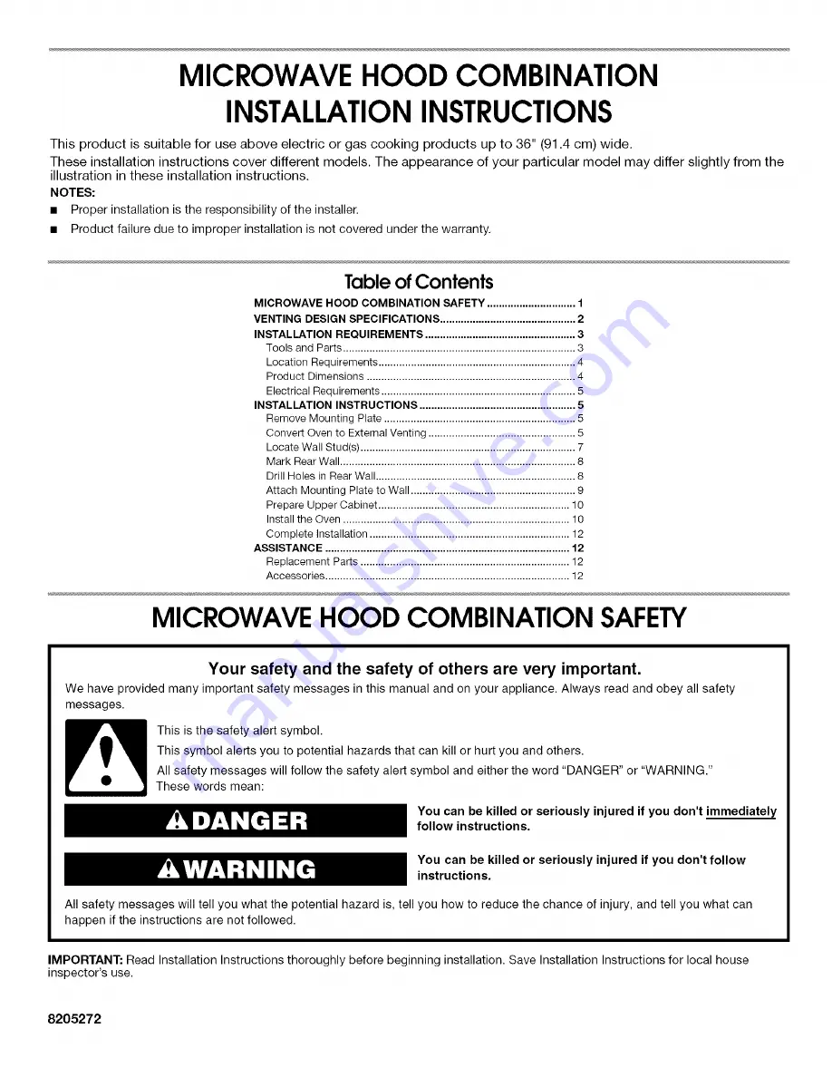
Page 1: ... 9 Prepare Upper Cabinet 10 Installthe Oven 10 Complete Installation 12 ASSISTANCE 12 ReplacementParis 12 Accessories 12 MICROWAVE HOOD COMBINATION SAFETY Your safety and the safety of others are very important We have provided many important safety messages in this manual and on your appliance Always read and obey all safety messages This is the safety alert symbol This symbol alerts you to poten...

Page 2: ...ng compound to seal exterior wall or roof opening around cap not installing 2 elbows together for optimal hood performance If venting through the wall be sure that there is proper clearance within the wall for the damper to open fully If venting through the roof and rectangular to round transition is used be sure there is at least 3 7 6 cm of clearance between the top of the microwave oven and the...

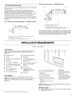
Page 3: ...eded Gather the required tools and parts before starting installation Read and follow the instructions provided with any tools listed here Measuring tape Diagonal cutting pliers Pencil Stud finder Masking tape or thumbtacks 7 16 socket wrench or box wrench for 1 4 x 2 Scissors lag screws T10TORX rscrewdriver 11 2 4 cm diam hole drill No 3 Phillips screwdriver for bit for wood or metal 1 4 20 x 3 r...

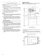
Page 4: ...ements For Wall Venting Installation Only The 12 x 4 30 5 x 10 2 cm cutout area see Wall Venting Installation Only in the Mark Rear Wall section must align with the wall damper vent on the back of the oven see Wall Venting Installation Only in the Convert Oven to External Venting section Cutout must be free of any obstructions so that the vent tube fits properly and the damper blade opens freely a...

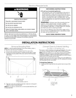
Page 5: ...nsion cord If the power supply cord is too short have a qualified electrician or serviceman install an outlet near the microwave oven SAVE THESE INSTRUCTIONS INSTALLATIONINSTRUCTIONS l 8emov 1VSo Jnt ng NOTE To avoid possible damage to the work surface place a protective cover on the work surface 1 Remove any remaining contents from the oven cavity 2 Remove the mounting plate by peeling off the st...

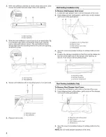
Page 6: ...er vent cover D Perforations 3 Save the cover for possible change of venting method in the future 4 Position the damper assembly so that the long tab slides into the slot on the right side of the damper vent opening as shown Then secure with mounting screw 4 A Vent opening B Vent deflector Secure vent deflector with 2 mounting screws 1 on each end A B A Mounting screw B Vent deflector 5 Replace ve...

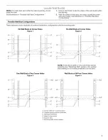
Page 7: ...xamples of preferred installation configurations with the mounting plate No Wall Studs at Corner Holes Figure 1 No Wall Studs at Corner Holes Figure 2 NOTE If wall stud is within 6 15 2 cm of the vertical centerline see Mark Rear Wall section only ventless recirculating or roof venting installation can be done One Wall Stud at Two Corner Holes Figure 3 i i i i i i i i i I i i Wall Studs at All Fou...

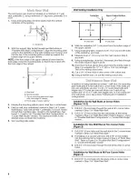
Page 8: ... Step 6 and mark 9 Using a straightedge draw the 2 horizontal level lines through the marks made in steps 6 and 8 10 Draw the 2 vertical plumb lines down from the marks made in Step 7 to complete the 12 x 4 30 5 x 10 2 cm rectangle This is the venting cutout area 11 Cut a 3 4 19 mm hole in one corner of the cutout area 12 Using a keyhole saw cut out the venting cutout area In addition to being ins...

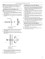
Page 9: ...ud at Two Corner Holes in the Drill Holes in Rear Wall section 2 Start toggle nuts on the bolts from the back of the mounting plate Leave enough space for the toggle nut to go through the wall and to open 3 Position mounting plate on the wall making sure that the top of the mounting plate is aligned with the front edge of the upper cabinet 4 Push the 2 bolts with toggle nuts through the drywall an...

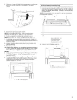
Page 10: ...pply cord bushing needs to be installed around the supply cord hole as shown A A Metal cabinet B Power supply cord bushing 6 Drill 3 8 10 mm holes at points D and E on the template These are for two 1 4 20 x 3 round head bolts and washers used to secure the oven to the upper cabinet For Roof Venting Installation Only 7 Cut 3 4 19 mm hole at one corner of the shaded rectangular area F on Upper Cabi...

Page 11: ... 7 If adjustment is required rotate oven downward Using 2 or more people lift oven off of mounting plate and set aside on a protected surface 8 Loosen mounting plate screws Adjust mounting plate and retighten screws 9 Repeat steps 3 6 10 With the oven centered and with at least one person holding it in place insert bolts through upper cabinet into oven Tighten bolts until there is no gap between u...

Page 12: ...8205274 Mounting Screw Kit includes parts A G in Parts Supplied section Part Number 8205979 Vent Deflector Part Number 8205980 2 3 4 5 Plug microwave oven into grounded 3 prong outlet Reconnect power Check the operation of microwave oven by placing 1 cup 250 mL of water on the turntable and programming a cook time of I minute at 100 power Test vent fan and exhaust by operating the vent fan If the ...

Reviews: