WIA W64-1, Operator'S Manual
Introducing the WIA W64-1 Operator's Manual, a comprehensive guide to mastering the features and functions of this incredible product. Available for free download from 88.208.23.73:8080, unleash the full potential of your device with this essential manual. Equip yourself with the knowledge to maximize your product experience.
Share
Download


Reviews:
No comments
Related manuals for W64-1
MM 300-ES
Brand: Comparc Pages: 28
BECMATIC 550
Brand: BecherAir Components Pages: 17

AKM 96RM-E
Brand: janitza Pages: 76
OTC CM-741U
Brand: Daihen Pages: 34

Dillon Conversion Kit
Brand: RCBS Pages: 12
Streamfeeder Value Series
Brand: Barry-Wehmiller Pages: 58
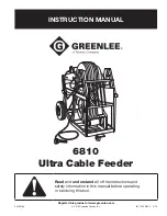
Greenlee 6810
Brand: Textron Pages: 26
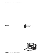
VR 2000
Brand: Fronius Pages: 42
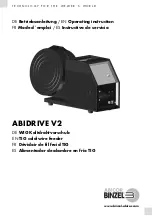
ABIDRIVE V2
Brand: Abicor Binzel Pages: 136
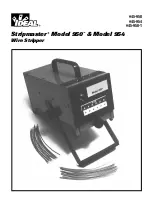
Stripmaster 950
Brand: IDEAL Pages: 16
GEK-106273L
Brand: GE Pages: 209

Power Feed 10 Robotic K1780-2
Brand: Lincoln Electric Pages: 28
76202
Brand: Lincoln Electric Pages: 13
K2536-6
Brand: Lincoln Electric Pages: 59
DADF-G1
Brand: Canon Pages: 154
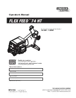
FLEX FEED 74 HT
Brand: Lincoln Electric Pages: 59
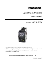
YW-50DNW
Brand: Panasonic Pages: 20

SJ-WBFG-RED
Brand: sunjoe Pages: 20


