Montageanleitung (Original)
Assembly Instruction (Translation based on original documentation)
gesis
FLEX-FC EM
83.020.0639.0
KNX - FanCoil Erweiterungsmodul
KNX - FanCoil extension Module
Wieland Electric GmbH
Brennerstraße 10-14
96052 Bamberg
Tel.: +49 (951) 9324-0
Fax: +49 (951) 9324-198
Internet: www.wieland-electric.com
Email: info@wieland-electric.com
Doc. # BA001018- 09/2015 (Rev. A)
gesis
KNX FLEX-FC EM
DE/EN 1
GEFAHR
•
Nur Elektrofachkräfte dürfen dieses Gerät installieren und in Betrieb nehmen. Vor
Ausführung müssen sie diese Anleitung gelesen und verstanden haben.
•
Gerät nicht öffnen. Keine Fremdobjekte einführen. Gerät von Wasser und Feuer fernhalten.
•
Gerät nur in spannungsfreiem Zustand anschließen oder trennen.
•
Die einschlägigen Normen, Richtlinien, Vorschriften und Bestimmungen des jeweiligen
Landes sind zu beachten.
Das FanCoil Erweiterungsmodul im flachen, auf Tragschiene montierbaren AP-Gehäuse zum
dezentralen Einbau kann ein Heiz-/Kühlventil und ein Zusatzrelais steuern. Es stellt einen
Binäreingang und einen Temperatursensoreingang zur Verfügung. Die nach IEC 61535 steck-
baren, elektrischen Verbindungen trennen Automation und Installation.
Hinweis: Dieses Modul kann nur zusammen mit dem Grundmodul gesis KNX FLEX-FC
(83.020.0638.0) betrieben werden
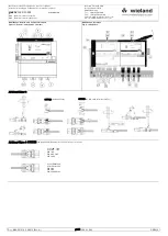
Bedien- und Funktionselemente (siehe Rückseite, Abbildung 1)
Taster ' '
' 'kurzer Tastendruck inkrementiert den Wert am Ventilausgang.
Taster 'relay'
Ein Tastendruck toggelt im manuellen Betrieb den Relaisausgang.
Taster ' '
' 'kurzer Tastendruck dekrementiert den Wert am Ventilausgang.
Rastfuß
Arretierung für Montage auf Tragschiene/Montagerahmen
'status input'
Die LED leuchtet grün.. Der zu überwachende Kontakt ist geschlos-
sen. (Fensterkontakt / Taupunktwächter)
Die LED ist aus. Der angeschlossene Kontakt ist offen.
'valve overload'
LED leuchtet rot bei statischer Überlast am Ventilausgang.
Sensoreingang
Anschluss für Temperatursensor NTC
'input'
An diesem Binäreingang können potentialfreie Kontakte angeschlos-
sen werden.
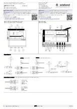
'valve 2'
Wahlweise für Ventil 0…10 V oder PWM. Anschluss vom Stecker
GST15i3 siehe Abbildung 3+4
'relay' Ausgang
Dieser zusätzliche AC 230 V Ausgang erlaubt den Anschluss von
weiteren Verbrauchern bis zu einem Laststrom von max. 5A.
Montage (siehe Rückseite, Abbildung 2)
Schritt 1:
Verbinden der Module
1.1
Linke Schutzabdeckung aufstecken und einrasten (Abb. 2)
1.2
Erweiterungsmodul am Grundmodul anreihen und hörbar einrasten (Abb. 2).
1.3
Rechte Schutzabdeckung am Erweiterungsmodul montieren (Abb .2)
Schritt 2:
Optional: Befestigung auf Tragschiene oder Montagerahmen
2.1
Mit Schraubendreher Rastfuß am Modul nach oben ziehen.
2.2
Modul auf Tragschiene setzen.
2.3
Rastfuß nach unten drücken. Module sind auf der Tragschiene montiert.
Schritt 3:
Kabel stecken und sichern
3.1
Kabel entsprechend seiner Codierung stecken.
3.2
Kabel am Erweiterungsmodul entsprechend seiner Codierung stecken.
3.3
Bei Montagerahmen: Kabel mit Kabelbindern am Montagerahmen befestigen.
Technische Daten
Versorgung
Das Erweiterungsmodul wird vom Grundmodul
gesis KNX FLEX-FC (83.020.0638.0) mit allen zum Betrieb und
für die Sensoreingänge notwendigen Spannungen versorgt.
Temperatursensoreingang '
q
'
Spannung
24 VDC (- 10 % / +20 %) intern
Sensortyp
NTC 6K8 B25/100 = 4200 K
Leitungslänge
max. 30 m
Binäreingang 'input' Kontaktüberwachung
Spannung
24 VDC (- 10 % / +20 %) intern
Strombegrenzung intern
6 mA
Leitungslänge
max. 30 m
Ventilausgang 'valve 2' Hinweis: Mischbetrieb ist nicht möglich
PWM
DC 24 V max 4,5 VA Belegung Pin 1 + 3 (GST15i3 braun)
0…10V
0V…10 V / max. 10 mA Belegung Pin 1 + 2 (GST15i3 braun)
Leitungslänge
max. 30 m
Relaisausgang
AC 230 V / max. 5A
maximale Schaltleistung
1250 VA
Umweltbedingungen
Einsatzbereich
Innenräume und trockene Räume, wettergeschützt
Klimabeständigkeit
Klasse 3K5 (EN 50491-2)
Umgebungstemperatur
-5 C bis +45 °C
Lagertemperatur
-25 C bis +70 °C
Montageart
Decken-, Boden-, Wandmontage, auf ebener Montagefläche
feste Installation, Aufputz, Tragschiene TH35-7,5
Gehäuse
Material
Kunststoff, halogenfrei
Farbe
Lichtgrau, ähnlich RAL 7035 / Schwarz, ähnlich RAL 9005
Brandverhalten
Brandlast
Abmessungen (L, B, H)
UL94 V-2
ca. 1,8 kWh (ohne Grundmodul)
290 mm, 149 mm, 44 mm (inklusive Grundmodul, Endkappen)
Elektrische Sicherheit
Schutzklasse
I
Schutzart
IP20 (nach EN 60529)
Verschmutzungsgrad
2
Überspannungskategorie
III
Zulassungen
KNX
KNX zertifiziert (in Verbindung mit dem Grundmodul)
CE-Kennzeichnung
Gemäß EMV-Richtlinie und Niederspannungsrichtlinie
Erfüllt Normen: EN 50491-5-1, EN 50491-5-2, EN 50491-5-3
Handbuch
mit detaillierten Informationen zu Programmierung, Inbetriebnahme und
Wartung:
•
Dokumentnummer: BA000903
•
Download über QR-Code oder:
http://eshop.wieland-electric.com/product/83.020.0639.0
DANGER
•
Only electricians may install and commission this device. You must have read these
instructions and understood them before carrying out the work.
•
Do not open the device or introduce any foreign objects. Keep away from water and fire.
•
Only connect or disconnect the device when the device is deenergized.
•
The relevant standards, guidelines, regulations and provisions of the respective country
must be observed.
The FanCoil extension module in the flat AP housing, which can be installed on mounting rails,
for decentralized installation, can control a heating/cooling valve and an additional relay. It
provides a binary input and a temperature sensor input. The plugged electrical connections, in
accordance with IEC 61535, separate the automation and installation. Note: this module can
only be operated in combination with the gesis KNX FLEX-FC (83.020.0638.0) basic module
Controls and functional elements (see reverse, Figure 1)
Button ' '
' 'short button press produces a positive incremental change to the
value at the valve output.
'relay' button
In manual mode, pushing the button toggles the relay output
Button ' '
' 'short button press produces a negative incremental change to the
value at the valve output
locking foot
Lock for mounting on DIN rail / mounting frame
'status input'
The LED lights up green.. The contact to be monitored is closed. (win-
dow contact / dewpoint monitor)
The LED is off.. The connected contact is open. The line length (twisted
pair) at the input must not exceed 30 m.
'valve overload' The LED lights up red with static overload at the valve outlet.
sensor input
Connection for temperature sensor NTC
'input'
Potential-free contacts can be connected to this binary input.
'valve 2'
Optional valve output for actuation of 0…10 V or PWM. Connection of
Plug GST15i3 see Fig. 3+4.
'relay' output
This additional 230 V AC output permits connection of additional
consumers, up to a maximum load current of 5A.
Assembly (see reverse, Figure 2)
Step 1:
Connecting the modules
1.1
Attach and latch left protection cover (Fig. 2)
1.2
Place the extension module on the basic module and click into location audibly (Fig. 2).
1.3
Mount the right-hand protection cover on the extension module (Fig. 2)
Step 2:
Optional: Fastening on mounting rail or assembly frame
2.1
Pull the locking foot on the module upwards using a screwdriver.
2.2
Place module onto mounting rail.
2.3
Push the locking foot downwards. Modules are mounted on the mounting rail.
Step 3:
Plug in cables and secure
3.1
Plug in the cable in accordance with its coding.
3.2
Plug in the cable on the extension module in accordance with its coding.
3.3
For assembly frames: use cable ties to fasten cables to the assembly frame.
Technical data
Supply
The extension module is supplied with all voltages required for
operation and for the sensor inputs by the
gesis KNX FLEX-FC
(83.020.0638.0) basic module.
Temperature sensor input '
q
'
Voltage
24 VDC (- 10 % / +20 %) internal
Sensor type
NTC 6K8 B25/100 = 4200 K
Length of line
max. 30 m
Binary input 'input' contact monitor
Voltage
24 VDC (- 10 % / +20 %) internal
Current limiting internal 6 mA
Length of line
max. 30 m
Valve output 'valve 2' Note: mixing mode is not possible
PWM
DC 24 V max 4.5 VA allocation Pin 1 + 3 (GST15i3 brown)
0…10V
0 V…10 V / max. 10 mA allocation Pin 1 + 2 (GST15i3 brown)
Length of line
max. 30 m
Relay output
AC 230 V / max. 5 A
Environmental conditions
Usage area
Indoors, in dry rooms, protected against weather
Climate resistance
Class 3K5 (EN 50491-2)
Ambient temperature
-5 C to +45 °C
Storage temperature
-25 C to +70 °C
Mounting method
Ceiling, floor, wall mounting, on even surface, fixed installation,
surface mounted (plaster), mounting rail TH35-7.5
Housing
Material
Plastic, halogen-free
Color
Light gray, similar to RAL 7035 / black, similar to RAL 9005
Fire resistance
Fire load
Dimensions (W, H, L)
UL94 V-2
approx. 1.8 kWh (without basic module)
290 mm, 149 mm, 44 mm (including basic module, end caps)
Electric safety
Protection class
I
Protection type
IP20 (as per EN 60529)
Pollution degree
2
Overvoltage category
III
Approvals
KNX
KNX certified (in combination with the basic module)
CE marking
According to EMC directive and low voltage directive
Standards complied with: EN 50491-5-1, EN 50491-5-2, EN 50491-5-3
Manual
with detailed information about programming, commissioning and
servicing:
•
Document number: BA000904
•
Download via QR code or:
electric.com/product/83.020.0639.0


