

Wieland Electric GmbH
Brennerstraße 10-14
96052 Bamberg
Tel.: +49 (951) 9324-0
Fax: +49 (951) 9324-198
Internet: www.wieland-electric.com
Email: info@wieland-electric.com
R1.100.4001.0
SMI 1001
Magnetschalter-Interface
Magnetic switch interface
04/2010 (Rev. B)
©2010 Wieland Electric GmbH
Doc. # BA000412
Seite 1
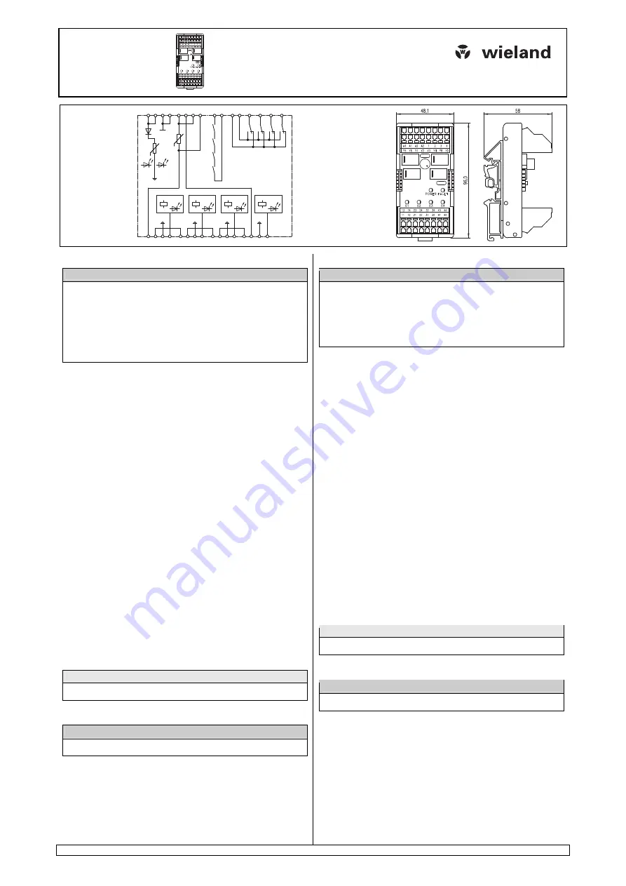
Blockschaltbild
Block diagram
K1
S1
K2
S2
K3
S3
K4
S4
A1 A1 A2 A2 1 2 Y8 Y9
11 12 13 14
V+
21 22 23 24
V+
31 32 33 34
V+
41 42 43 44
V+
3 4
Y4
Y3
Y2
Y1
Y6 Y5
V+
K1
K2
K3
K4
K4 K3
K2
K1
Power Fault
PTC
PTC
Abmessungen (mm)
Dimensions (mm)
DEU Montageanleitung
(Original-Betriebsanleitung)
A C H T U NG
•
Elektrische Installationen, Inbetriebnahme- und Wartungsarbeiten dürfen nur
von ausgebildeten Elektrofachkräften mit einschlägiger Unfallverhütungs-
Ausbildung und unter Beachtung der gültigen Vorschriften durchgeführt wer-
den.
•
Schutzmaßnahmen und Schutzeinrichtungen müssen den gültigen Vorschriften
entsprechen.
•
Beschädigte Produkte dürfen weder installiert noch in Betrieb genommen
werden.
•
Das Gerät darf nicht geöffnet werden.
•
Bei Anschlußarbeiten ist auf Spannungsfreiheit zu achten.
A)
Funktionsbeschreibung
Das SMI 1001 schaltet Sicherheitsschalter/Positionsschalter in Reihe. Damit
können mehrere Sicherheitsschalter oder Positionsschalter an Sicherheitsschalt-
geräte der Serie 4000 oder an die Sicherheitssysteme samos und samos PRO
angeschlossen und ausgewertet werden.
Das SMI 1001 verfügt über Statusanzeigen für den Schaltzustand der Schließer-
kreise der angeschlossenen Sensoren sowie über vier Diagnoseausgänge zur
Anzeige des Schaltzustands der Schließerkreise über externe LEDs oder eine
Steuerung.
B)
Bestimmungsgemäße Verwendung
Betreiben Sie das Gerät nur innerhalb der Spezifikationen (siehe "F) Technische
Daten").
An das SMI 1001 dürfen nur folgende Schalter/Taster angeschlossen werden:
•
max. 50 Sicherheitsschalter SMA 012x, SMA 022x, SMA 032x oder
•
max. 50 Positionsschalter mit Schließer-/Schließer-Kombination oder
•
max. 50 NOT-HALT-Taster mit Öffner-/Öffner-Kombination
Das SMI 1001 darf nur an folgende Auswertegeräte angeschlossen werden:
•
SNO 4062K/KM
•
SNO 4063K/KM
•
SNA 40xxK/KM
•
SNV 4063KL/KP
•
SNV 407xSL
•
SNV 4274SL
•
SNV 4074ST sowie
•
an Module der Serie samos und samos PRO
Möchten Sie mehr als vier Sicherheitsschaltern/Positionsschalter anschließen,
schalten Sie die SMI 1001 in Reihe. Es dürfen maximal 13 SMI 1001 in Reihe
geschaltet werden. Ab dem zweiten Gerät müssen Sie die Anschlüsse Y8 und Y9
brücken.
Falls Sie weniger als vier Sicherheitsschaltern/Positionsschaltern an einem SMI
1001 anschließen, überbrücken Sie freie Schließereingänge.
H I N W E I S
Der Einsatz des SMI 1001verringert die Klassifizierung nach EN 60947-5-3 von
PDF-M auf PDF-S.
C)
Montage
A C H T U NG
Montieren Sie das Gerät in einen Schaltschrank mit einer Schutzart von mindes-
tens IP54.
•
Befestigen Sie das Gerät mit Hilfe des Rastelements auf der Rückseite auf einer
Normschiene.
•
Sichern Sie das Gerät auf einer senkrechten Tragschiene (35 mm) durch ein
Halteelement (z. B. Endhalter oder Endwinkel).
ENG Installation instructions
(Translation of the original instructions)
A T T E N T I O N
•
Electric installations, placing devices into operation and maintenance tasks may
only be carried out by qualified electricians with relevant training in accident
prevention and while adhering to applicable regulations.
•
Protective measures and mechanisms must correspond to applicable regula-
tions.
•
Damaged products may neither be installed nor operated.
•
The device may not be opened.
•
Ensure that the device is de-energized before connection work.
A)
Functional description
The SMI 1001 switches safety switches /position switches in series. Thus several
safety switches or position switches can be connected to the series 4000 safety
relays, or to the safety systems samos and samos PRO, and evaluated.
The SMI 1001 features status indicators for the switch status of the N/O circuits of
the connected switches, and four diagnostic outputs to display the switch status of
the N/O circuits via external LEDs or a PLC.
B)
Intended use
Operate the device only within the specifications (refer to "F) Technical data").
Only the following devices may be connected to the SMI 1001:
•
max 50 safety switches SMA 012x, SMA 022x, SMA 032x
•
max 50 position switches with N/O / N/O combination in safety circuits
•
max 50 E-STOP buttons with N/C / N/C combination
The SMI 1001 may only be connected to the following evaluation devices:
•
SNO 4062K/KM
•
SNO 4063K/KM
•
SNA 40xxK/KM
•
SNV 4063KL/KP
•
SNV 407xSL
•
SNV 4274SL
•
SNV 4074ST and
•
to samos und samos PRO series modules.
If you want to connect more than four safety switches/position switches, connect
SMI 1001 in series. A maximum of 13 SMI 1001 is allowed for series connection.
From the second SMI 1001 on, link Y8
−
Y9.
If connecting less than four safety switches/position switches, link out the free N/O
inputs on the SMI 1001.
N O T E
The use of SMI 1001 lowers classification in accordance with EN 60947-5-3 from
PDF-M to PDF-S.
C)
Mounting
A T T E N T I O N
The unit should be installed in a control cabinet with a protection type of at least
IP54.
•
Use the notch on the back of the unit to attach it to a DIN rail.
•
On a vertical DIN rail (35mm), secure the unit using a retaining bracket or end
angle.


