background image

W h e r e   I n n o v a t i o n   F l o w s

www.wildenpump.com

EOM

Engineering

Operation &

Maintenance


WIL-12310-E-04

TO REPLACE WIL-12310-E-03

PX8

Sanifl o

 Hygienic Series

Metal Pumps

Summary of Contents for PX4 series

Page 1: ...W h e r e I n n o v a t i o n F l o w s www wildenpump com EOM Engineering Operation Maintenance WIL 12310 E 04 TO REPLACE WIL 12310 E 03 PX8 Saniflo Hygienic Series Metal Pumps...

Page 2: ...rve 9 Rubber Fitted 12 TPE Fitted 13 Full Stroke PTFE Fitted 14 Full Stroke SIPD Fitted 15 Reduced Stroke PTFE Fitted 16 Reduced Stroke SIPD Fitted 17 Reduced Stroke Ultra Flex Fitted 18 B Suction Lif...

Page 3: ...25 psig air supply pressure CAUTION The process fluid and cleaning fluids must be chemically compatible with all wetted pump components Consult Chemical Resistance Guide E4 CAUTION Do not exceed 82 C...

Page 4: ...SANITARY WIL FLEX 1 3 4 SF STAINLESS STEEL FLAP1 5 TF PTFE1 2 3 4 TM PTFE MUSHROOM CHECK1 2 MANIFOLD GASKET FB SANITARY BUNA N1 3 4 red dot FE SANITARY EPDM1 3 4 green dot FV SANITARY VITON 1 3 4 one...

Page 5: ...A reachesthelimitofitsdischarge stroke the air valve redirects pressurized air to the back side of diaphragm B The pressurized air forces diaphragm B away from the center while pulling diaphragm A to...

Page 6: ...CHARGE PX8 Saniflo HS Flap Valve Fixed DIMENSIONS ITEM METRIC mm STANDARD inch A 460 18 1 B 213 8 4 C 577 22 7 D 902 35 5 E 955 37 6 F 51 2 0 G 579 22 8 H 363 14 3 J 559 22 0 K 46 1 8 L 401 15 8 M 351...

Page 7: ...METRIC mm STANDARD inch A 460 18 1 B 247 9 7 C 612 24 1 D 938 36 9 E 989 38 9 F 51 2 0 G 615 24 2 H 498 19 6 J 693 27 3 K 46 1 8 L 401 15 8 M 351 13 8 N 394 15 5 P 432 17 0 R 10 0 4 DIMENSIONS ITEM M...

Page 8: ...g with a pump that wasn t designed to transfer sanitary solids Are your inspection cleaning and maintenance costs too high Are you looking for a pump that is actually designed for your application Wil...

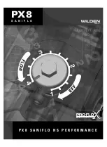
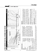
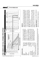
Page 9: ...PX8 P X 8 S A N I F L O H S P E R F O R M A N C E S A N I F L O...

Page 10: ...ility that exceeds previous industry standards Pro Flo XTM Operating Principle S e c t i o n 5 A Turning the dial changes the relationship between air inlet and exhaust porting Each dial setting repre...

Page 11: ...this case 9 8 scfm Step 2 Determining flow and air X Factors Locate your discharge pressure 40 psig on the verti cal axis of the EMS curve Figure 2 Follow along the 2 8 bar 40 psig horizontal line un...

Page 12: ...psig discharge pressure After locat ing this point on the flow curve draw a verti cal line downward until reaching the bottom scale on the chart and identify the flow rate In our example it is 38 6 lp...

Page 13: ...different than the flow point plotted in example 2 1 After estimating or interpolating this point on the curve draw a vertical line downward until reaching the bottom scale on the chart and identify...

Page 14: ...tween the setting curves for operation at intermediate EMS settings EXAMPLE A PX8 Sanifl o HS full stroke Rubber fi tted pump operating at EMS setting 4 achieved a fl ow rate of 348 lpm 92 gpm using 1...

Page 15: ...for specifi c applications The pump is delivered with the EMS adjusted to setting 4 which allows maximum fl ow The EMS curve allows the pump user to deter mine fl ow and air consumption at each EMS se...

Page 16: ...e performance of your Wilden pump for specifi c applications The pump is delivered with the EMS adjusted to setting 4 which allows maximum fl ow The EMS curve allows the pump user to determine fl ow a...

Page 17: ...used to optimize the performance of your Wilden pump for specifi c applications The pump is delivered with the EMS adjusted to setting 4 which allows maximum fl ow The EMS curve allows the pump user...

Page 18: ...ng curves for operation at intermediate EMS settings EXAMPLE A PX8 Sanifl o HS reduced stroke PTFE fi tted pump operating at EMS setting 4 achieved a fl ow rate of 257 lpm 68 gpm using 170 Nm 3 h 100...

Page 19: ...can be used to optimize the performance of your Wilden pump for specifi c applications The pump is delivered with the EMS adjusted to setting 4 which allows maximum fl ow The EMS curve allows the pump...

Page 20: ...timize the performance of your Wilden pump for specifi c applications The pump is delivered with the EMS adjusted to setting 4 which allows maximum fl ow The EMS curve allows the pump user to determin...

Page 21: ...t is meant to be a guide only There are many variables which can affect your pump s operating characteristics The number of intake and discharge elbows viscosity of pumping fluid elevation atmospheric...

Page 22: ...N O T E S...

Page 23: ...ve and the pump to bleed off which improves pump performance MUFFLER Sound levels are reduced below OSHA specifications using the standard Wilden muffler Other mufflers can be used to further reduce s...

Page 24: ...p the pump from operating in an emergency situation simply close the air shut off valve user supplied installed in the air supply line A properly functioning valve will stop the air supply to the pump...

Page 25: ...to identify pumps that are poorly suited to their applications Pump will not run or runs slowly 1 Ensure that the air inlet pressure is at least 0 4 bar 5 psig above startup pressure and that the diff...

Page 26: ...g it upside down and allowing any fluid to flow into a suitable container Be aware of any hazardous effects of contact with your process fluid NOTE The model photographed for these instructions incorp...

Page 27: ...ve housing mushroom valve and gasket Step 6 Loosen the wing nut and remove the inlet manifold clamp bands Step 7 Next remove the clamp bands that secure the ball valve housing to the liquid chamber St...

Page 28: ...remove one of the two outer pistons Step 11B If your pump is fitted with an IPD the procedure for removing the diaphragm is slightly different In this case simply grasp the diaphragm in two locations...

Page 29: ...E N S O R Step 1 After removing the inlet and discharge manifold assemblies disconnect the Wil Gard module from the sensor wires Wil Gard Diaphragm Sensor Removal Step 2 Next remove the large clamp ba...

Page 30: ...Prior to installing the liquid chamber and after positioning theWil Gard sensor cable between the primary and back up diaphragms run the sensor cable along the diaphragm bead but outside the pump Now...

Page 31: ...s Drain the pump by turning it upside down and allowing any fluid to flow into a suitable container Be aware of hazardous effects of contact with your process fluid Step 1 Using a 9 16 wrench loosen t...

Page 32: ...f the air valve Step 7 Remove the air valve spool from the air valve body by threading one air valve bolt into the end of the air valve spool and gently sliding the spool out of the air valve body Ins...

Page 33: ...t solutions Our unique network enables us to purchase effectively resulting in low cost solutions We also know that low purchase price is not enough quality integrity and inventory are also important...

Page 34: ...g See Figure A Open the pliers as wide as the seal diameter will allow then with two fingers pull down on the top portion of the seal to form kidney bean shape See Figure B Lightly clamp the pliers to...

Page 35: ...diaphragm failure The following are some details to consider when cleaning the PX8 HS pump Through the EHEDG certification process the PX8 HS pump has been validated to clean equivalent to the inlet t...

Page 36: ...E W PA R T S L I S T I N G WILDEN PUMP ENGINEERING LLC 34 WIL 12310 E 04 SWIVEL STAND OPTION FLAP MUSHROOM FULL STROKE RUBBER TPE FULL STROKE IPD W 3 A BACK UP FULL STROKE IPD REDUCED STROKE IPD W 3...

Page 37: ...385P 24 T Section 2 EHEDG 2 08 5160 10 385P 08 5160 10 385P 08 5160 10 385P 08 5160 10 385P 08 5160 10 385P 08 5160 10 385P T Section 2 EHEDG DIN 2 08 5160 10 386P 08 5160 10 386P N A 08 5160 10 386P...

Page 38: ...tand 4 08 7670 20 08 7670 20 N A 08 7670 20 08 7670 20 N A 48 Washer Flat 406 X 812 X 065 2 04 6740 03 04 6740 03 N A 04 6740 03 04 6740 03 N A 49 Screw HHC 3 8 16 X 1 1 4 2 04 6190 03 04 6190 03 04 6...

Page 39: ...04 1060 54 blue dot N A 04 1020 54 blue dot 08 1086 74 2 blue dots 08 1375 74 green dot 15 1375 74 green dot SANIFLEX 04 1010 56 cream 04 1060 56 cream 04 1065 56 cream N A 08 1086 56 cream N A N A P...

Page 40: ...of this authorization for the use of the 3 A Symbol is based upon the voluntary certification by the applicant for it that the equipment listed above complies fully with the 3 A Sanitary Standards des...

Page 41: ......

Page 42: ...N O T E S WILDEN PUMP ENGINEERING LLC 40 WIL 12310 E 04...

Page 43: ...comes rst Failure due to normal wear misapplication or abuse is of course excluded from this warranty Since the use of Wilden pumps and parts is beyond our control we cannot guarantee the suitability...

Reviews: