background image


U

U

S

S


P

P

C

C

S

S


R

R

e

e

p

p

e

e

a

a

t

t

e

e

r

r


S

S

y

y

s

s

t

t

e

e

m

m


Manual 


W

W

i

i

r

r

e

e

l

l

e

e

s

s

s

s


D

D

a

a

t

t

e

e


C

C

o

o

m

m

m

m

u

u

n

n

i

i

c

c

a

a

t

t

i

i

o

o

n

n


C

C

o

o

.

.

,

,


L

L

t

t

d

d

.

.


2

2

0

0

0

0

5

5

.

.


0

0

7

7

.

.


Summary of Contents for US-PCS-S1

Page 1: ...U US S P PC CS S R Re ep pe ea at te er r S Sy ys st te em m Manual W Wi ir re el le es ss s D Da at te e C Co om mm mu un ni ic ca at ti io on n C Co o L Lt td d 2 20 00 05 5 0 07 7 ...

Page 2: ...ar ri io on n a an nd d O Ob bs se er rv va at ti io on n 1 13 3 3 3 S Sy ys st te em m S St ta an nd da ar rd ds s 1 14 4 3 3 1 1 E El le ec ct tr ro on ni ic c F Fe ea at tu ur re es s 1 14 4 4 4 T Th he e O Op pe er ra at ti io on n o of f E Eq qu ui ip pm me en nt t 1 16 6 4 4 1 1 T Th he e O Or rd de er r o of f E Eq qu ui ip pm me en nt t I In ns st ta al ll la at ti io on n 1 17 7 4 4 2 2 T...

Page 3: ...To improve the equipment install expenses and efficiency utility Service signal among ultra mixed PCS signal of other operation preferentially amplify and relay to the shadow area so that it would be provided good quality service economically efficiently This repeater is using method by converting the weak RF signal from the Base Station into IF band amplifying and then resending the RF signal It ...

Page 4: ...Installment Application and maintenance z Built in Antenna z Convenient Automatic Set up Programmed 2 The Structure of Equipment Functional Features The Repeater system is for the relaying system that can supply the services Tx Rx 1850 1910MHZ Tx Rx 1930 1990MHz by one equipment This is installing a wide service of 120MHz bandwidth in the shade area between the ...

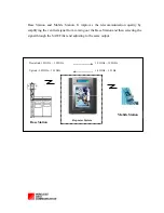
Page 5: ...ty by amplifying the verified signal from coming out the Base Station and then selecting the signal through the SAW Filter and adjusting to the same output Mobile Station Repeater System Downlink 1 93GHz 1 99GHz Uplink 1 85GHz 1 91GHz 1 93GHz 1 99GHz 1 85GHz 1 91Hz Base Station ...

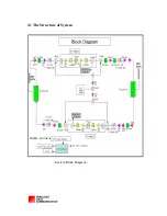
Page 6: ...18 6 2 1 The Structure of System System Block Diagram ...

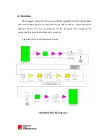
Page 7: ...he Base Station and amplifying first step after filtering the other company s signal through the Duplexer Down Converter converting the RF into IF signal Amp amplifying the power and PLL Local for the Down Up converting The functions for each block are as follows Downlink Block Diagram ...

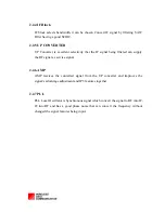
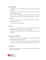
Page 8: ...on from the terminal is KTF 1930 MHz 1990 MHz Tx Rx Isolation is more than 50 dBc 2 2 2 LNA LNA is as a AMP amplifying first step received the weak signals through the DUPLEXER has a excellent specific device of NF 1dB under It improves the whole system of NF and IP3 is rather high that can come out the stable output 2 2 3 DOWN CONVERTER Down Converter would convert IF signal from low noise amplif...

Page 9: ...eing filtered can supply the RF signal as service signal 2 2 6 AMP AMP receives the converted signal from the UP converter and improves the signal s advantage adjustment and IP3 features together 2 2 7 PLL PLL Local Oscillator is Synchronous signal which convert the signal to RF into IF IF into RF and has a good phase noise that can convert the frequency without changed the signal features being i...

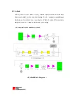
Page 10: ...e Base Station and amplifying first step after filtering the other company s signal through the Duplexer Down Converter converting the RF into IF signal HPA amplifying the power and PULL Local for the Down Up converting The functions for each block are as follows Up link Block Diagram ...

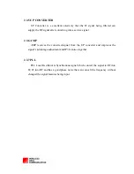
Page 11: ...ation is more than 50 dBc 2 3 2 LNA LNA is as a AMP amplifying first step received the weak signals through the DUPLEXER has a excellent specific device of NF 1dB under It improves the whole system of NF and IP3 is rather high that can come out the stable output 2 3 3 DOWN CONVERTER Down Converter would convert IF signal from low noise amplified signal for filtering SAW Filter having a good SCIRT ...

Page 12: ...e signal 2 3 6 AMP AMP receives the converted signal from the UP converter and improves the signal s advantage adjustment and IP3 features together 2 3 7 PLL PLL Local Oscillator is Synchronous signal which convert the signal to RF into IF IF into RF and has a good phase noise that can convert the frequency without changed the signal features being input ...

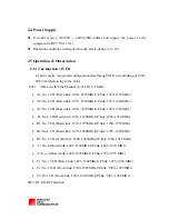
Page 13: ...0 1935 MHz A2 No 2 CH Down link 1855 1860MHz UP link 1935 1940 MHz A3 No 3 CH Down link 1860 1865MHz UP link 1940 1945 MHz D No 4 CH Down link 1865 1870MHz UP link 1945 1950 MHz B1 No 5CH Down link 1870 1875MHz UP link 1950 1955 MHz B2 No 6 CH Down link 1875 1880MHz UP link 1955 1960 MHz B3 No 7 CH Down link 1880 1885MHz UP link 1960 1965 MHz E No 8 Down link 1885 1890MHz UP link 1965 1970 MHz F N...

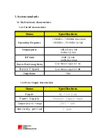
Page 14: ... 7 5V 2 4A Power Specifications Items 20 C 40 C 1 year Temperature range Warranty period 50Ω Impedance Less than or equal to 1 ms Port to Port Group Delay 60dB Up link 60dB Down link RF Gain Less than or equal to 5 dB Noise Figure 8dBm Down link 18dBm Up link Output power 1930MHz 1990MHz Down link 1850MHz 1910MHz Up link Operating Frequency Specifications Items ...

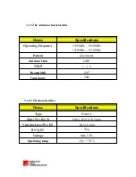
Page 15: ... 5 VSWR 50Ω Impedance 8dBi Antenna Gain directional Pattern 1930MHz 1990MHz 1850MHz 1910MHz Operating Frequency Specifications Items Max 5 5V Voltage 45g Weight 20 70 C Operating temp 64 x 16 mm Viewing Area W x H 80 0 x 36 0 x 10 5 mm Sizw W x H x T Positive Type Specifications Items ...

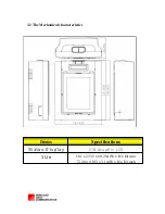
Page 16: ...18 16 3 2 The Mechanical characteristics 181 x 233 5 x 80 254 W x H x D mm 7 126 x 9 193 x 3 14 W x H x D inch Size STN Graphic LCD Status Display Specifications Items ...

Page 17: ...the Base Station and outputting to the mobile terminal forward relaying the received signal from the mobile terminal and outputting to the Base Station Backward INFORMATION TO THE USER Note The manufacturer is not responsible for any Radio or TV interference caused by unauthorized modifications to this equipment Such modifications could void the user s authority to operate the equipment CAUTION RF...

Page 18: ...em Check out the VFD connection and if not problem replace 5 2 Does not come out the signal on repeater Î Cause When the repeater not RF ON When the channel 1 12CH of repeater doesn t meet the signal from the BTS Î Correction Turn on the repeater system on pressing the channel switch 2 Press the channel switch 1 and go though the work from 1 12 Check out the connection part of power in the PCS of ...

Reviews: