background image

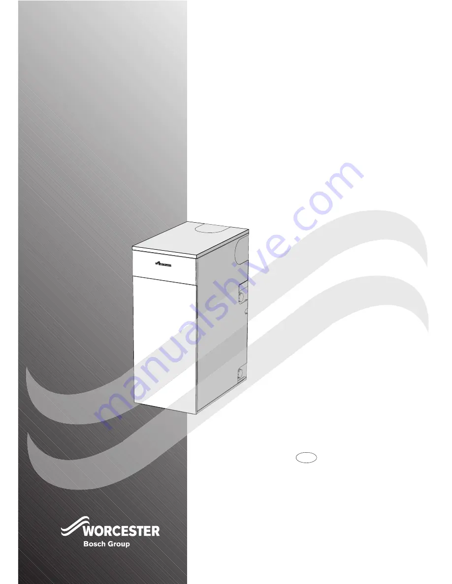
GREENSTAR UTILITY

18/25kW

FLOOR STANDING OIL-FIRED CONDENSING BOILER

CONVENTIONAL FLUE & ROOM SEALED FLUE

FOR FULLY PUMPED OPEN VENT OR SEALED CENTRAL HEATING SYSTEMS AND DOMESTIC

HOT WATER CYLINDERS

THE APPLIANCE IS FOR USE WITH 28 SECOND KEROSENE
ONLY

GB/IE

8-716-106-256a (08.05)

INSTRUCTION MANUAL

INSTALLATION COMMISSIONING

& SERVICING

GB

Patent pending:
Application number 0327645.8

THE APPLIANCE IS FOR USE WITH 28 SECOND KEROSENE

Patent pending:
Application number 0327645.8

THE APPLIANCE IS FOR USE WITH 28 SECOND KEROSENE
ONLY

GB/IE

INSTRUCTION MANUAL

GB

Summary of Contents for GREENSTAR UTILITY

Page 1: ...HOT WATER CYLINDERS THE APPLIANCE IS FOR USE WITH 28 SECOND KEROSENE ONLY GB IE 8 716 106 256a 08 05 INSTRUCTION MANUAL INSTALLATION COMMISSIONING SERVICING GB Patent pending Application number 032764...

Page 2: ...tinel FLUE TERMINAL GUARDS WORCESTER BOSCH Part Number 7 716 190 050 CONVENTIONAL FLUE MANUFACTURERS INTERACTIVE Flue Systems Ltd 01908 569887 Selkirk Manufacturing Ltd SF Ltd 01271 326633 CONDENSATE...

Page 3: ...0 CONDENSATE PRESSURE RELIEF PIPEWORK 11 BOILER LOCATION CLEARANCES 12 13 FLUE OUTLET POSITIONS 14 CONVENTIONAL FLUE 15 ROOM SEALED FLUE OPTIONS 16 INSTALLATION UNPACKING THE BOILER 17 PIPEWORK POSITI...

Page 4: ...conomy safety and reliability of the appliance Failure to install appliances correctly could lead to prosecution The appliance should be installed by a competent person The person installing the appli...

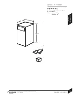
Page 5: ...G INSTRUCTIONS FOR WORCESTER BOSCH 3 GENERAL INFORMATION GENERAL INFORMATION 8 716 106 256a 08 05 STANDARD PACKAGE A Floor standing oil fired condensing boiler B Literature pack C Hardware pack includ...

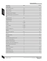
Page 6: ...pressure bar Flue Exit flue gas mass flow kg hr Pipework connections Fuel line compression mm CH flow inch BSP CH return mm CH vent Optional inch BSP CH drain inch BSP Condensate polypropylene mm Elec...

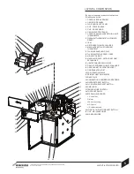
Page 7: ...AMPLING POINT 13 FLUE MANIFOLD ACCESS COVER 14 AIR INLET CASING 15 MANUAL AIR VENT SECONDARY HEAT EXCHANGER 16 HEAT EXCHANGER FLOW PIPE 17 DRAIN SECONDARY HEAT EXCHANGER 18 REAR CABINET SUPPORT BRACKE...

Page 8: ...M Fill the system with cold mains water to the recommended pressure and check for leaks Open all drain cocks and drain the system Close drain cocks and add a suitable flushing agent at the correct str...

Page 9: ...liance must be earthed All pipes to the boiler must be cross bonded It must be possible to isolate the appliance from the electric supply with at least a 3mm contact separation in all poles supplying...

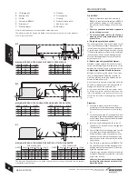
Page 10: ...on the oil level must be at least 300mm above the oil pump J Where the maximum oil level in the oil storage tank exceeds 4 metres a head breaking device must be installed between the tank A and the bu...

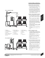
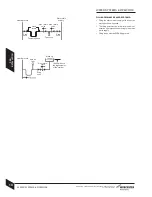
Page 11: ...oints on the system Air vents are required at all high points on the system OPEN VENT PRIMARY SYSTEM The feed and expansion cistern E must be positioned to provide a static head S of at least 1 metre...

Page 12: ...of the methods shown opposite The filling point must be at low level and must never be a permanent direct fixing to the mains water supply Filling loops must be WRAS approved Heating return Hose retur...

Page 13: ...ate route A Condensate from boiler B Sink C 21 5mm polypropylene condensate pipe D Gully E Internal soil and vent stack F Condensate trap 75mm min G 300mm x 100mm sealed plastic tube H Ground level J...

Page 14: ...aken from another room that room must contain an air inlet as described above Room sealed balanced flue model RS The appliance does not require a separate vent for combustion air Installation in cupbo...

Page 15: ...be provided for boilers fitted into compartments as described in BS 5410 Free air must not be taken from a room or internal space containing a bath or shower and must not communicate with a protected...

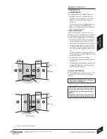
Page 16: ...stance of the flue terminal to a facing wall fence building or property boundary is 2500mm FLUE OUTLET POSITIONS 14 FLUE OUTLET POSITIONS 1 An opening means an openable element such as an openable win...

Page 17: ...the working temperature minimum rating of material 120 C of the appliance and any condensate which may form All flue joints must be sealed to prevent the leakage of condensate and combustion products...

Page 18: ...Terminal Kit incl 90 elbow Calculating the flue length Measure the total flue length required noting that the maximum straight flue length including the terminal is Horizontal 80 125mm 4000mm excludin...

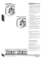
Page 19: ...upwards off the top supporting ledge and store safely away from the working area At least two or more persons are required to move the boiler taking care not to damage the boiler panels or the floor A...

Page 20: ...rge pipes away from components and pipework connections FLUE OPENING Follow the diagram opposite to mark the centre of the flue 1 2 for rear opening 2 3 for side opening or 1 4 for top opening IMPORTA...

Page 21: ...ead N from heat exchanger and store safely away from the boiler 7 Release split pin to remove the flue thermostat M from the flue hood 8 Release split pins P Carefully remove the overheat thermostat p...

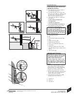
Page 22: ...FLUE KITS 80 100 103mm not supplied CF Vertical flue kit Part No 7 716 190 036 INSTALLATION NOTES Ensure all flue seals are in good condition and seated properly To ease assembly of flue components g...

Page 23: ...d baffle retainer D are correctly fitted for the boiler output as shown in the plan view opposite 3 Refit combustion chamber door A Secure with nuts and washers B and tighten until the door is firmly...

Page 24: ...either side of the boiler as required and connect to the isolating valve E Ensure the valve is closed Connect the flexible oil pipe F to the isolating valve E CONDENSATE CONNECTION Measure condensate...

Page 25: ...he pump is factory set for single pipe operation with the flexible oil pipe fitted Check connections before use Connecting the oil pump for a double pipe system 1 Check the inlet pipe connection a DAN...

Page 26: ...r thermostat pocket Refit split pins P to secure 3 Carefully replace the flue thermostat M into the flue hood and refit split pin to secure 4 Align burner combustion head N into boiler housing tube wi...

Page 27: ...to 6mm 230V connections 3 Connect SWITCHED LIVE wire Brown or Red to terminal L Connect NEUTRAL wire Blue or Black to terminal N Connect EARTH wire Green Yellow to the terminal Route the power cable t...

Page 28: ...RESET THERMOSTAT E TERMINAL CONNECTOR BLOCK F CONTROL THERMOSTAT G BURNER CONTROL SOCKET H BURNER CONTROL PLUG IN CONNECTOR J BURNER CONTROL BOX 26 ELECTRICS ELECTRICS 8 716 106 256a 08 05 1 2 3 1 2 3...

Page 29: ...ng pump External programmer E TERMINAL CONNECTOR BLOCK Remote 10 way junction box K requirements the junction box K must be a terminal block type current rated to at least 5 amps a 5 amp fuse must be...

Page 30: ...tank and check the oil supply pipework connections and rectify any leaks 3 Check the flue is correctly fitted and the connections are secure 4 Check the condensate pipework is correctly fitted and co...

Page 31: ...on the water to the system header tank and allow the system to fill 2 Sealed systems only Fill the system to between 1 and 2 bar pressure via a WRAS approved filling link Check the expansion vessel p...

Page 32: ...a de aerator disconnect the flexible oil inlet hose nearest to the de aerator and place in a container of the same fuel oil Place an empty container to collect oil from the oil inlet pipe connection...

Page 33: ...1 If the smoke level is above 1 check the combustion settings are correct and the oil nozzle is in good condition Note smoke readings may be inaccurate until the smoke from burning organic binder in t...

Page 34: ...mer to ON for CH Turn the thermostat control A to max The burner should be ON with the circulating pump Ensure all radiators are heating up evenly and balance the system to the temperature difference...

Page 35: ...INHIBITOR Central Heating 4 Check drain cocks are closed and all radiator valves are open 5 Add a suitable inhibitor I or combined inhibitor anti freeze if the system is exposed to freezing conditions...

Page 36: ...secure 4 Locate the top panel F onto the ball stud connections G and press down to secure Handover Complete the Guarantee Registration Card Set up the controls and show the user how to operate all th...

Page 37: ...g screws C from each side of the control box G Slide control box G outwards to its full extent Pivot control box G upwards and secure in the service position as shown Operate the appliance and system...

Page 38: ...the check valve M are clear of any debris Check the condition of the O ring O Discard the check valve if the holes cannot be cleared if the unit is defective or if the O ring is damaged and replace w...

Page 39: ...r Release the M10 retaining nuts and washers B and remove combustion chamber access door A Check the fibreglass rope seal on the combustion chamber access door A and replace if necessary Remove and ch...

Page 40: ...cribed in STARTING THE APPLIANCE under the Commissioning section Refit panels 3 Unlock support L to pivot control box G and slide into the boiler Secure with screws C 4 Locate top edge of panel E onto...

Page 41: ...foss BFP 11 L3 Part Number 8 716 142 736 0 9 Transformer Excludes cable Part Number 8 716 156 696 0 10 Mechanical shut off valve Part Number 8 716 156 658 0 11 Flexible oil line kit Part Number 8 716...

Page 42: ...lace Air adjustment fault Incorrect CO Set up as in installation instructions No oil from nozzle No oil at pump Check and refill oil tank bleed oil line Check and clean filters valves from oil tank to...

Page 43: ...at bulb not fully home in pocket Ensure bulb is pushed fully home No primary water circulation Check system circulating pump Short Cycling Burner rating incorrect Correct burner rating Boiler thermost...

Page 44: ...Cotswold Way Warndon Worcester WR4 9SW Telephone 01905 754624 Fax 01905 754619 INSTRUCTION MANUAL INSTALLATION COMMISSIONING SERVICING Part Number Worcester Bosch Group is a trading name of BBT Thermo...

Page 45: ...25kW FLOOR STANDING OIL FIRED CONDENSING BOILER CONVENTIONAL FLUE ROOM SEALED FLUE FOR FULLY PUMPED OPEN VENT OR SEALED CENTRAL HEATING SYSTEMS AND DOMESTIC HOT WATER CYLINDERS THE APPLIANCE IS FOR U...

Page 46: ...WORCESTER BOSCH TEL FAX Service call centres UK 08547 256206 757536 SCOTLAND ONLY 01506 441687 EIRE 01494 0099 Other enquiries MAIN RECEPTION 01905 754624 754619 TECHNICAL 08705 266241 SPARES 01905 7...

Page 47: ...AS STANDARD 3 GENERAL INFORMATION 4 6 USING YOUR APPLIANCE CONTROLS 7 OPERATING THE APPLIANCE Switching the boiler on off 8 Setting the heating temperature 8 Controlling central heating 8 Frost prote...

Page 48: ...out by a competent engineer in accordance with the relevant Installation Regulations Flue systems must not be modified in any way other than as described in the fitting instructions Any misuse or unau...

Page 49: ...uality and proven reliability The condensing range in particular is extremely energy efficient converting more of the fuel consumed into heat offering you economical running costs and value for money...

Page 50: ...alidate the appliance guarantee Sealed heating systems Where the appliance is fitted to a sealed heating system your installer will inform you of the minimum and maximum pressure which must be indicat...

Page 51: ...ust not be restricted or contaminated The appliance clearances must meet the minimum shown opposite for servicing and venting purposes If this clearance is less than 75mm the flue knock out panel sect...

Page 52: ...ate with a protected area such as a hall stairway landing corridor lobby shaft etc Air vents must allow access for clean free air and must be sited to comply with the flue terminal position requiremen...

Page 53: ...rature control behind front top panel B Reset button burner lock out indicator reset button on burner control box under top panel C Reset button flue overheat thermostat behind front panel D Reset but...

Page 54: ...left unused and exposed to freezing conditions shut off all the mains supplies isolate the boiler and drain the system and boiler SETTING TEMPERATURE Turn the control clockwise to increase the water...

Page 55: ...E APPLIANCE 8 716 106 257a 08 05 OPERATING THE APPLIANCE 9 FROST PROTECTION Use a suitable anti freeze inhibitor at the correct strength to protect against freezing A frost thermostat should be fitted...

Page 56: ...b Lockout indicator OFF boiler not on no heating hot water 1 Ensure there is a power supply to the boiler 2 Check the programmer is set to on for heating 3 Press the reset buttons C D 4 If the boiler...

Page 57: ...loss from a property is through the roof Replace any old insulation with new insulation preferably to a minimum thickness of 200mm Window frames Single glazed windows particularly those with steel fra...

Page 58: ...to drape over the radiator or shelves are fitted above it The positioning of furniture and tables in front of the radiator should also be avoided It is advisable to manually adjust all radiator valves...

Page 59: ...sure it continues to operate at peak efficiency and performance it is essential that servicing and maintenance checks are performed at least once a year by a competent person beyond the initial guaran...

Page 60: ...se temperature control setting Air trapped in heating system Bleed radiators and recharge heating system Desired room temperature exceeded by large amount Radiators are too hot Turn down thermostatic...

Page 61: ...lied by BBT Themotechnology UK Ltd Note NO APPLIANCE FAULT IS FOUND ON OVER 30 OF ALL SERVICE CALL OUTS Please read this guide carefully to gain a good understanding of the operation of your appliance...

Page 62: ...missioned and where appropriate that the 12 month service inspection has been carried out to the satisfaction of BBT Thermotechnology UK Ltd when requested The guarantee card must then be returned wit...

Page 63: ...in 30 days of purchase Returning the card will register you as the owner of your new appliance and will assist us in maintaining an effective and efficient customer service by establishing a reference...

Page 64: ...ONS CUSTOMER CARE GUIDE Part Number Worcester Bosch Group Cotswold Way Warndon Worcester WR4 9SW Worcester Bosch Group is a trading name of BBT Thermotechnology UK Ltd www worcester bosch co uk 8 716...

Reviews: