

Workrite Ergonomics | 800.959.9675 www.workriteergo.com
1 of 12
Box 1
Box 2
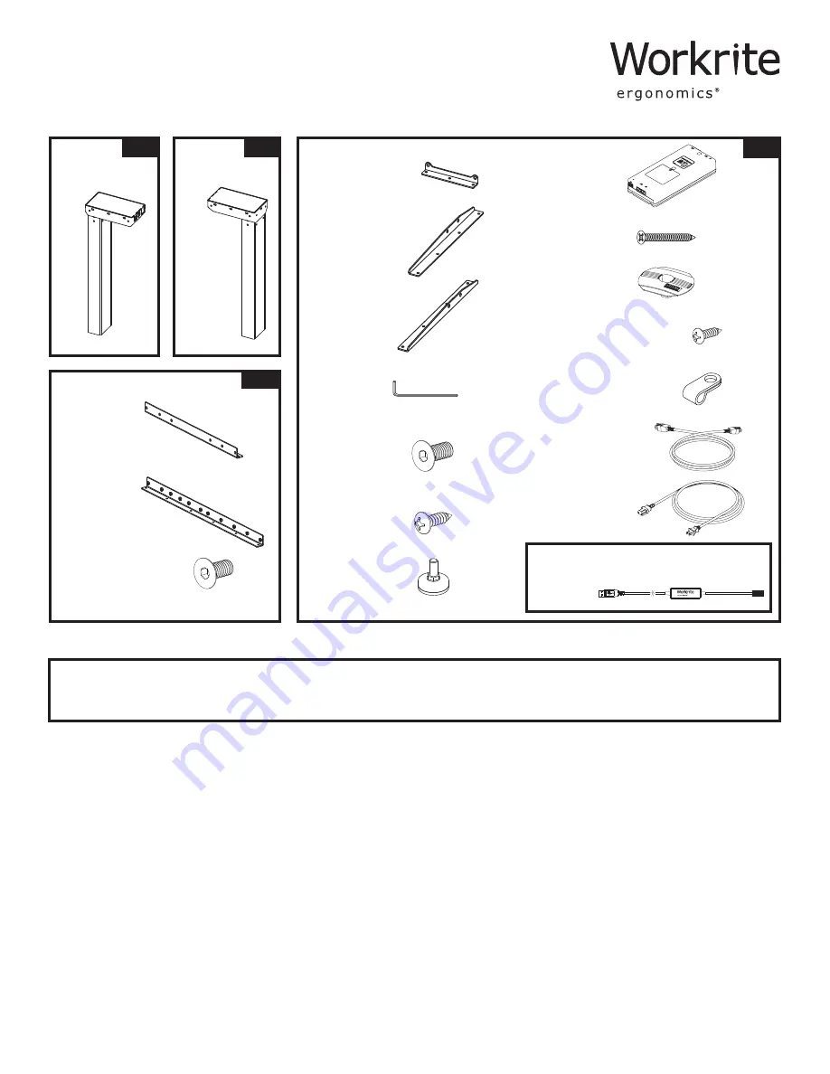
Box 4
Box 3
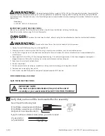
Parts Included
Required & Sold Separately
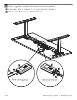
Q
Rear Bracket
Qty: 2
R
Connector Bracket
Qty: 1
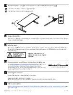
A
Leg
Qty: 1
A
Leg
Qty: 1
S
#M6 × 12 mm Flat
Head Cap Screw
Qty: 8
Assembly & Installation Instructions:
Sierra 2-Leg Workcenter SEHX54–72*, SEHXL54-72
Styled or Flat Foot Kit
Standard or Programmable Switch
Worksurface
E
4 mm Allen Wrench
Qty: 1
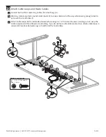
N
Leg Cable, 1
meter
Qty: 2
O
Power Cord
Qty: 1
K
Cable Spool
Qty: 2
M
3/16" Cable Loops
Qty: 10
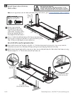
B
Short Bracket
Qty: 2
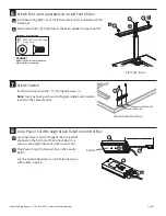
I
Control Box
Qty: 1
H
Foot Glide
Qty: 4
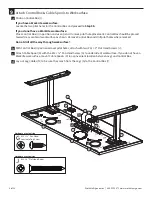
C
Left End Bracket
Qty: 1
D
Right End Bracket
Qty: 1
F
#M6 × 14 mm Flat Head Cap
Screw
Qty: 20
L
#8 × ⅝" Pan Head Screw
Qty: 12
G
#12 × ¾" Pan Head Laminate
Top Screw
Qty: 38
J
#12 × 2" Flat Head Screw
Qty: 2
P
*Sierra Interface Kit Cable included
with HX models
Qty: 1


