150716
For additional product information visit
wyrestorm.com
For technical support contact:
North America: +1 844-280-WYRE (9973) EMEA/ROW: +44 (0) 1793 230 343
KEY
HDMI
HDBaseT Cat6
Power
IR RX
IR TX
LAN / RS232
Speaker Cable
Audio Cable
Phono Cable
In the Box
1 x MX-0808-PP-POH-CUSTOM main unit + 8 x custom card selections
(as specified via the ‘GoConfigure’ Virtual Rack webtool or physical order
sheet sent to your WyreStorm representative)
Printed quickstart guide (full instruction manual downloadable form
wyrestorm.com)
2 x Matrix mounting brackets
1 x 100-240v AC power supply
1 x IR Extension cable
8 x IR TX emitters
8 x IR RX Receivers
1 x MX-0808-PP-POH-CUSTOM remote control incl. battery
Source Device
2
3
5
12
3
5
12
Power
6
7
RX-70-POH
Optional
Power
3
5
12
Transmission Device
4
Source Device
1
Source Device
10
1
See full manual for details
on EDID Management and
DIP settings.
Source Device
1
10
8
IR / Serial based
Control System
11
9
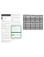
Attention: Open out for installation diagram.
Before Installation
Do Not Hotplug! - Please insert and extract cables carefully with
the power SWITCHED OFF. Connecting and disconnecting while
the unit is powered can result in damage to circuitry.
We strongly recommend using the supplied mounting brackets to
secure the matrix and the accompanying display receivers. Any
sudden movement of these devices could lead to loss of picture
and sound if connections become loose or strained, resulting in
unnecessary service call backs
Remember, always switch off the matrix before unplugging any
inputs or outputs – follow last on, first off protocol.
Basic Connection and Operation
Attention: Due to the customizable nature of this product, we
strongly suggest consulting the full instruction manual before
installation.
Based on your individual module configuration, connect multi-
format sources to Inputs 1-8 of the matrix using quality cables - we
recommend the use of WyreStorm Express HDMI cables.
To cascade HDMI transmission to another matrix an HDMI Pass-
through module is required.
For HDBaseT Outputs, connect a good quality, well-terminated Cat6
cable of no more than 70m/230ft from matrix HDBT OUT ports 1-8
to HDBT ports of connected display receivers.
If connecting a remote source via an HDBaseT Input module, ensure
Cat6 cable of no more than 70m/230ft is used between the HDBT
transmission device and HDBT IN of the matrix module. The matrix
uses PoH to remotely power PoH-enabled transmission devices so
no additional mains power is required at remote source locations
NOTE: Although WyreStorm products are tested with Cat5e,
we recommend Cat6 as standard due to increased bandwidth
and improved capacity for handling large transmissions along
a single cable.
At display locations, connect HDMI display devices to the HDMI OUT
ports of receivers.
NOTE: AMP-001-010 HDBaseT digital audio amplifier
receivers can be used for enhanced audio connectivity.
Connect the matrix to a mains power supply using the power cable
included and switch on the Power at the rear of the unit.
Check the front panel LED display is lit to indicate the matrix is ready
for use.
The matrix uses PoH to remotely power PoH-enabled receivers so
no mains power is required at display locations.
In instances where cable quality, length or placement impacts on
successful PoH delivery, or if using a non-POH enabled receiver,
units can be powered locally via threaded or phoenix 12v DC power
connectivity.
Check POWER, STATUS & LINK lights are illuminated on the receiver
to indicate successful connection, with a lit HDCP illustrating the
presence of encryption within the signal
NOTE: STATUS and HDCP LEDs should blink, POWER and
LINK are static LEDs.
Basic I/O switching is achieved via the matrix front panel. OUTPUTS
are selected by pressing the LEFT and RIGHT arrow buttons to scroll
forwards and backwards numerically through the displays connected
to the matrix. The corresponding OUTPUT channel number will blink
on the display when reached.
UP and DOWN arrow buttons scroll numerically through any INPUT
sources connected to the system. When the desired OUTPUT and
INPUT is reached, push the ENTER button to confirm the selection.
The display will stop blinking to confirm matrix I/O has been set.
Basic Signal IR/RS232 Control
Connect IR emitters from the matrix IR TX ports to the IR receiving
areas of sources, firmly attaching emitter eyes onto sources.
For use with a control system, IR Link cables (sold separately) should
be connected from the matrix IR RX ports to the controller used. For
an RS232-based control system, RS232 cables should be used from
matrix to control system and between receivers and display device.
At display locations, connect IR emitters from the display receiver
IR TX ports to the IR receiving areas of the display device and IR
receivers from IR RX ports on/near the device with clear line of sight
to the handset used to control.
NOTE: Emitter eye position on device IR receiving areas may
need to be adjusted later to achieve best IR performance.
See full instruction manual for detailed instructions on connection,
operation and control.
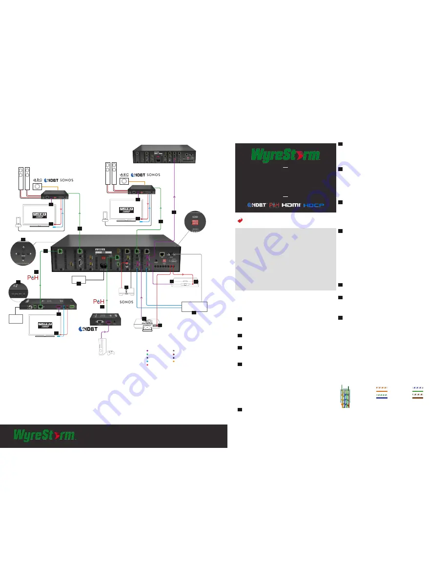
Wiring and Connections
HDBaseT Wiring
Wiring for HDBaseT follows the EIA T568B standard.
IMPORTANT! Wiring Guidelines
• The use of patch panels, wall plates, cable extenders, kinks in cables,
and electrical or environmental interference can have an adverse effect
on HDBaseT transmission limiting performance. Steps should be taken
to minimize these factors (or remove completely) during installation for
best results.
1
2
3
4
5
6
7
8
9
10
11
12
Quickstart Guide
WyreStorm 8-Slot HDBaseT Modular Matrix Chassis
with 2-way IR, Routed RS232 and PoH
MX-0808-PP-POH-CUSTOM
Pin 1 Pin 8
RJ-45 Connector (Gold Pins Facing Up)
Pin 2: Orange
Green
Pin 6:
Pin 1: White/Orange
Pin 5: White/Blue
Pin 3: White/Green
Pin 7: White/Brown
Pin 4: Blue
Pin 8: Brown