background image

X – 60 Instructions Version 1.0 

Page 1


X – 60

CONVERSION KIT 

X – 60   ASSEMBLY 


INSTRUCTIONS


Version 1.0  


www.2wdrc.com 

Summary of Contents for X-60

Page 1: ...X 60 Instructions Version 1 0 Page 1 X 60 CONVERSION KIT X 60 ASSEMBLY INSTRUCTIONS Version 1 0 www 2wdrc com...

Page 2: ...ion 1 0 Page 2 TABLE OF CONTENTS T4 Disassembly 5 Bag A Transmission Assembly 12 Front End Installation 17 Bag B Bulkhead Transmission Install 20 Bag C Rear Suspension Assembly 25 Bag D Final Assembly...

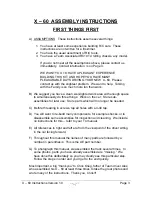
Page 3: ...on the car Store sub assemblies for later use Store parts which will no longer be needed C Before threading in screws tap all holes with a 4 40 tap D You will want to re build many components for exam...

Page 4: ...ts who love working on their cars trying new things and helping others at the track We communicate with our Family constantly and the Family gives us ideas every day for new products and improvements...

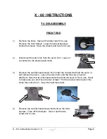
Page 5: ...d to the steering bell crank 3 Remove the two flat head screws from under the chassis that hold the servo in and remove the servo Leave the servo horn and the two servo mounts attached Save the two fl...

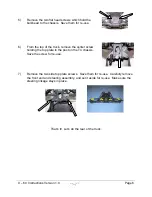
Page 6: ...p of the truck remove the center screw holding the top plate to the post on the T4 chassis Save the screw for re use 7 Remove the two side top plate screws Save them for re use Carefully remove the fr...

Page 7: ...for re use Slide the shocks off the bolts and save the mounting bushings for re use 10 Remove the nuts that hold the shock bolts in the tower Remove the bolts and save the bolts nuts bushings and pla...

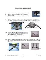
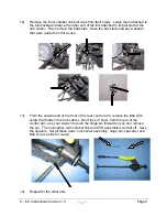
Page 8: ...hat were under them for re use 13 From the outside end of the front of the rear control arm remove the little 2 56 screw that holds in the hub carrier Don t lose it Now from the rear of the control ar...

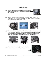
Page 9: ...e You will not need the spur gear but you must save all the other parts for re use 17 From under the truck remove the two flat head screws that hold the motor guard Then from above remove the two butt...

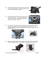
Page 10: ...the mounts if you wish or just loosen and twist the mounts out of the way for step 21 21 From the top put your wrench down between the body mounts and remove the two cap head screws that secure the t...

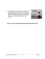
Page 11: ...p shaft spacer and two 3 8 X 3 16 bearings Idler gear two more 3 8 X 3 16 bearings idler shaft Ball differential and two X 5 8 outdrive bearings You will need all the parts from inside the transmissio...

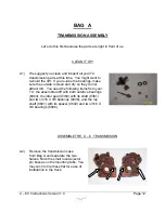
Page 12: ...n and dry so they do not attract dirt You need the following items from your T4 the assembled diff with both outdrive bearings 6903 the idler gear 9360 with its shaft 9361 and two 3 16 X 3 8 bearings...

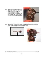
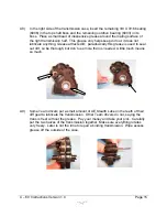
Page 13: ...in the left transmission case half The Team pushes them in with the shank of an Allen driver or better yet with a socket See Inst A5 Install an outdrive bearing 6903 in its boss A4 Make sure the spac...

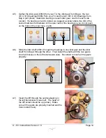
Page 14: ...es the diameter of the outer race of the bearing so you do not push on the balls or the inner race right A6 Slide the idler shaft 9361 through the bearings in one idler gear and the idler shaft from B...

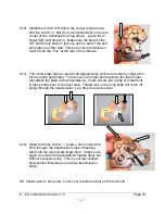
Page 15: ...se attracts dirt paradoxically this grease is used to seal out dirt so be thorough but don t use more than is needed A little touch means so much A9 Some Team drivers put a small amount of AE Stealth...

Page 16: ...stall a fan for the motor left photo The arrows in the right photo point to the three holes that attach the plate to the transmission Team drivers put a drop of thread lock in these holes prior to the...

Page 17: ...all the way through the four battery hold down posts and will secure the battery hold down strap It is easiest to do this now and they won t be in the way later A14 Position the T4 front suspension an...

Page 18: ...screws finger tight for now A16 Carefully turn the chassis front suspension over Install the two 5 8 flat head screws you removed from the bulkhead back into the rear most of the four holes at the fro...

Page 19: ...X 60 Instructions Version 1 0 Page 19 A18 Now secure the three screws for the top plate that you left finger tight in step A14 above That s it front end is done...

Page 20: ...e to tap lightly to fully seat the inserts The inserts should remain in place through the transmission install and it s easiest to do them now The rearmost holes in the chassis will be used later they...

Page 21: ...The hexes face forward and fit in the molded hexes in the bulkhead Note that half of the hex is molded into the bulkhead and half into the chassis Keep the bulkhead upside down for instruction B4 B4...

Page 22: ...and motor plate in its box It should be a snug fit but should slide up and down without too much force Check that nothing is catching The motor plate should be snug against the right side of the motor...

Page 23: ...head bolts and flat washers Leave these bolts finger tight for now B9 Place a flat washer about half way on the last 4 40 X 5 8 cap head bolt Slide the spacer under the right rear transmission mounti...

Page 24: ...t apply final torque to all four transmission mounting bolts B11 Install the flat head from instruction 17 through the motor plate and motor plate support You may need to loosen the two bolts that hol...

Page 25: ...e choose one and put the shock mounting holes to the rear You ll need the hinge pin 9622 two spacers 4187 and the little 2 56 button head screw C2 Check the Tuning Section and Set Up sheets for hub sp...

Page 26: ...ss bushings When these photos were taken only the plastic prototypes were available Insert the brass bushings into the rear of the chassis one on each side of the transmission box Photos show the tran...

Page 27: ...as been supplied with two toe in bars 3 degrees and 4 degrees Check the Tuning Section and Set Up sheets to determine which you will use Engage the rear of the hinge pins in their holes in the toe in...

Page 28: ...et anti squat You have a bag with four 060 and two 030 shims which allow you to make 030 increments from zero to 150 In the left photo we have a 030 and a 060 to make 090 Secure the toe in bar and shi...

Page 29: ...with body mounts forward using four 4 40 X cap head bolts two from bag two from instruction 21 In a few bulkheads these screws have stripped when over tightened so don t be a gorilla here Prototype t...

Page 30: ...rd and back Check the Tuning Section and Set up sheet to see which you will use These photos show the servo in the forward position The servo installs with the two saved flat head screws from the bott...

Page 31: ...S C long arrow in the center of the chassis just ahead of the battery slot If your receiver will fit in front of the E S C we suggest you place it in the center too We have supplied two antenna mounts...

Page 32: ...our body mounts then use your ream to make the four holes for the posts If you are using an FM radio there is a small dimple for your antenna tube Use the body clips you saved They re around here some...

Page 33: ...and rear ride heights based on the remainder of the set up rather than dogbone angle considerations Included in Bag B is a Ziplock bag of transmission shims four each of 030 060 090 and 120 Counting z...

Page 34: ...degrees but rather we discuss the number of inches of shim Once again you should adjust anti squat early in your preparation for a race taking into consideration dogbone angle IT S ALL ABOUT WEIGHT DI...

Page 35: ...blow away those normal trucks There is one advantage to a rear motor car in the first five feet after a corner weight pivots back on acceleration reducing the car s tendency to fishtail On most track...

Page 36: ...X 60 Instructions Version 1 0 Page 36...

Reviews: