background image

Please read and understand this instruction manual carefully 

before the installation and operation of this equipment.

© Xcel-Arc 2021

VIPER TIG 200P 

DC INVERTER WELDER

Operating Manual | XA-TIG200VP

YEAR

MACHINE

WARRANTY

1

1

YEAR

MACHINE

WARRANTY

Summary of Contents for VIPER TIG 200P

Page 1: ...rstand this instruction manual carefully before the installation and operation of this equipment Xcel Arc 2021 VIPER TIG 200P DC INVERTER WELDER Operating Manual XA TIG200VP YEAR MACHINE WARRANTY 1 1 YEAR MACHINE WARRANTY ...

Page 2: ...orised repair agent as appointed by this company Warranty does not cover abuse misuse accident theft general wear and tear New product will not be supplied unless ESSETI New Zealand Limited has inspected product returned for warranty and agrees to replace product Product will only be replaced if repair is not possible Please view full Warranty term and conditions supplied with machine or at www Xc...

Page 3: ...NE PARTS LAYOUT 8 FRONT PANEL FUNCTIONS 9 INSTALLATION SET UP FOR MMA STICK WELDING 11 MMA STICK WELDING GUIDE 13 INSTALLATION SET UP FOR TIG WELDING 15 TIG WELDING GUIDE 17 XA17 TIG TORCH SPARES 24 TIG WELDING SPARES 26 GAS FLOW REGULATORS SHEILDING GASES 27 MMA STICK WELDING TROUBLE SHOOTING 28 TIG WELDING TROUBLE SHOOTING 29 WARRANTY TERMS 31 NOTES 34 VIPER 200P TIG Welder Manual 3 CONTENTS ...

Page 4: ...wer cable for wear and tear replace the cable immediately if damaged bare wiring is dangerous and can kill Do not use damaged under sized or badly joined cables Do not drape cables over your body We recommend RCD safety switch is used with this equipment to detect any leakage of current to earth Fumes and gases are dangerous Smoke and gas generated whilst welding or cutting can be harmful to peopl...

Page 5: ...se gas cylinders are normally part of the welding cutting process be sure to treat them carefully CYLINDERS can explode if damaged Protect gas cylinders from excessive heat mechanical shocks physical damage slag open flames sparks and arcs Insure cylinders are held secure and upright to prevent tipping or falling over Never allow the welding cutting electrode or earth clamp to touch the gas cylind...

Page 6: ...rature inside the equipment The machine will be ready for use again when the internal temperature reaches safe level iii Over Voltage Supply Regarding the power supply voltage range of the machine please refer to Main parameter table This equipment is of automatic voltage compensation which enables the maintaining of the voltage range within the given range In case that the voltage of input power ...

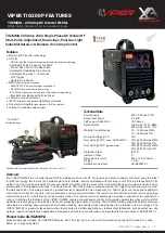
Page 7: ...welds including cast Iron stainless and low hydrogen The VIPER TIG200P is a semi professional machine that is suited to multiple applications stainless steel fabrication light industrial use site welding repair and maintenance applications Designed and built to our specification and manufactured in compliance to AS NZ60974 1 XA TIG200VP Standard Package TIG MMA 200 Amp 230V Single Phase DC Welder ...

Page 8: ...nal Positive Output Terminal Gas Quick Connect Control Knobs Right Front Foot Handle Front Plastic Gaurd Right Rear Foot Fan Gaurd Machine Metal Cover Rear Panel Gas Input Rear Plastic Gaurd On Off Switch Cable Protector Input Cable Fan Left Rear Foot Left Front Foot Front Panel Front Panel Grill 8 VIPER 200P TIG Welder Manual MACHINE PARTS LAYOUT ...

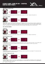
Page 9: ...s 2 actions of the torch switch refer to page 10 for instruction of 2T function 4T Select the 4T icon using the selector pad 4T uses 4 actions of the torch switch refer to page 11 for instruction of 4T function PANEL Push the pad to select the PANEL icon This provides adjustment of the welding amps by using the adjustment knob on the machine REMOTE Push the pad to select the REMOTE icon This provi...

Page 10: ... output from 10 160 Amps displayed by the digital meter TIG Down Slope Control TIG Down Slope Turning the knob sets the transition time from welding amps to minimum amps when finishing the weld The value selected shows on the digital display and can be set from 0 5 seconds It is the amount of time taken for the welding to drop down to minimum amps TIG Pulse Frequency Turning the knob adjusts the a...

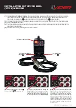
Page 11: ... by the electrode manufacturer 5 Set the arc force by rotating the Arc Force Knob 3 Select DC MMA Function Push the button until the DC icon glows red 4 Set the weld amperage by rotating the Amps Knob Set the amperage according to the electrode type and size being used as rec ommended by the electrode manufacturer The set amperage will show in the Digital Display 5 Set the arc force by rotating th...

Page 12: ... to cool and carefully chip away the slag to reveal the weld metal below 6 Connect the Earth Clamp securely to the work piece or the work bench 6 Connect the Earth Clamp 7 Place the electrode into the electrode holder and clamp tight 8 Strike the electrode on the work to create the arc and hold the electrode steady to maintain the arc 9 Hold the electrode slightly above the work piece to maintain ...

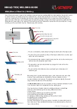
Page 13: ...ode metal is transferred across the arc into the molten pool and becomes the deposited weld metal The deposit is covered and protected by a slag which comes from the electrode coating The arc and the immediate area are enveloped by an atmosphere of protective gas Core wire Flux coating Base metal Protective gas Arc Slag Weld pool Manual metal arc stick electrodes have a solid metal wire core and a...

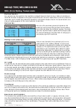
Page 14: ...eral rule of thumb for down hand welding is to have an arc length no greater than the diameter of the core wire Electrode Angle The angle that the electrode makes with the work is important to ensure a smooth even transfer of metal When welding in down hand fillet horizontal or overhead the angle of the electrode is generally between 5 and 15 degrees towards the direction of travel When vertical u...

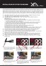
Page 15: ...7 Connect the gas line to the quick lock gas inlet connector at the rear of the machine Connect gas line to Gas Regulator and connect the gas regulator to the Gas Cylinder 7 Connect the gas line to the machine Connect the regulator to the cylinder Connect the gas lead to the regulator Set the flow to 10 15 l min 4 Connect the Earth cable connector to the terminal 5 Connect the torch switch lead to...

Page 16: ...he torch switch 1 Pressing the torch switch gives arc ignition and initializes the welding current 2 Releasing the torch switch continues the welding operation 3 Pressing the torch switch and holding introduces down slope and current falls to minimum current 4 Releasing the torch switch terminates the welding operation and introduces the post flow gas 3 Choose the preferred welding current amperag...

Page 17: ...ld pool TIG welding offers the user the greatest amount of flexibility to weld the widest range of material and thickness and types DC TIG welding is also the cleanest weld with no sparks or spatter HF ARC IGNITION for TIG tungsten inert gas Welding HF high frequency ignition allows the arc to be started in Tig welding without touching the tungsten to the work piece By pressing the torch switch th...

Page 18: ... heat input Background Amps is a percentage of peak amperage As a rule use enough background current to reduce the weld pool to about half its normal size while still keeping the weld pool fluid As a guide start by setting the background amperage at 20 to 30 percent of peak amperage Pulse Frequency is the control of the amount of times per second Hz that the welding current switches from Peak Curr...

Page 19: ...ding of how each variable affects the welding current Time 1 Second Hz 1 Select DC Pulse by pushing selector button to cycle through to illuminate DC Pulse icon 2 Select the Peak Amps using the Amps control knob 3 Rotate the Adjustment Knob to set the Peak Amps at 100A Range is 10 200 Amps 4 The Peak Amps are now set at 100 Because the Base Amp is preset in the machine at 40 it means that the Base...

Page 20: ...pool 75 15 Form a weld pool Travel direction Angle torch Add Tig filler wire Retract the filler wire Move the torch forward to the front of the weld pool Repeat the process gas shield TIG Welding Fusion Technique Manual TIG welding is often considered the most difficult of all the welding process es Because the welder must maintain a short arc length great care and skill are re quired to prevent c...

Page 21: ... arc starting electrode lifetime and overall cost effectivenes When E3 Tungsten Electrodes are compared with 2 thoriated tungsten E3 requires fewer re grinds and provides a longer overall lifetime Tests have shown that ignition delay with E3 Tungsten Electrodes actually improves over time while 2 thoriated tungsten starts to deteriorate after only 25 starts At equivalent energy output E3 Tungsten ...

Page 22: ...hwise and thus grinding crosswise is grinding against the grain If electrodes are ground crosswise the electrons have to jump across the grinding marks and the arc can start before the tip and wander Grinding longitudinally with the grain the electrons flow steadily and easily to the end of the tungsten tip The arc starts straight and remains narrow concentrated and stable grind longitudinal on th...

Page 23: ...nt on off switch hand amperage adjustment Type ER1MS 10 Type ER1MS 10H Type XA RFC 2 foot amperage adjustment Connection and operation of the remote hand control 3 Press the switch to activate the machine Rotate the amp control potentiometer to select the desired welding current 1 Push the Pad to select the Remote icon 1 Push the Pad to select the Remote icon Connection and operation of the remote...

Page 24: ...g Power Cable Connector 35 50 16 C03045 7 Pin Plug Spare Parts Part Number Description 1 XA17 Torch Body Standard XA17FX Torch Body Flexible 2 57Y02 Back Cap Long 2a 98W18 Back Cap O Ring 3 57Y05 Back Cap Medium 4 57Y04 Back Cap Short 5 ER1MS Momentary Switch Kit See page 174 for Switch options 6 ERSWL4 Trigger Lead x 4m ERSWL8 Trigger Lead x 8m 7 ERSP1 Screw Pack 8 ERH100 Small Ergo Tig Handle 2a...

Page 25: ...6 Gas Lens Collet Body 2 4mm 45V27 Gas Lens Collet Body 3 2mm 54N18L Long Gas Lens Nozzle Ø 6mm 4L 54N17L Long Gas Lens Nozzle Ø 8mm 5L 54N16L Long Gas Lens Nozzle Ø 10mm 6L 54N15L Long Gas Lens Nozzle Ø 11mm 7L 54N14L Long Gas Lens Nozzle Ø 12 5mm 8L Gas Lens Front End Parts 18CG Cup Gasket 54N01 Gas Lens Gasket USTB80300236 Gas Lens Gasket 10N22S Stubby Collet 1 0mm 10N23S Stubby Collet 1 6mm 10...

Page 26: ...Coil Each kit is supplied with compact Gas Lens parts for 1 6 2 4mm Tungstens RedNeck is ideal for the Stainless Steel Contractor and those looking for superior weld control with outstanding weld finish appearance All parts are available separately Contractors Kits are supplied in a convenient plastic compartment box with clip down lid Spare parts list and diagram is shown on inside of lid to assi...

Page 27: ...ding machine The amount of gas flow needed to do the job will depend on the welding gas and the job being done but a common setting to start with is 10 L min Shielding Gases Shielding gases are almost always necessary for MIG and TIG welding processes to protect the weld zone from gases that are contained in the surrounding atmosphere particularly nitrogen and oxygen If allowed into the weld zone ...

Page 28: ...age or choose a larger electrode Poor welding technique Use the correct welding technique or seek assistance for the correct technique Poor joint preparation Check the joint design and fit up make sure the material is not too thick Seek assistance for the correct joint design and fit up 6 Excessive penetration burn through Possible Reason Suggested Remedy Excessive heat input Reduce the amperage o...

Page 29: ...ce and colour Possible Reason Suggested Remedy Incorrect Gas Check that pure Argon is being used Inadequate gas flow gas leaks Check the gas is connected check hoses gas valve and torch are not restricted Set the gas flow between 10 15 l min flow rate Check hoses and fittings for holes leaks etc Moisture on the base metal Remove all moisture from base metal before welding Contaminated base metal R...

Page 30: ...NG Recommended Accessories XCEL ARC PROBAN WELDING JACKET XA BPJ TIG TORCH HOLDER MI TIGHOLD XCEL ARC TIG GLOVES XA 10 1003 L TOXIC WELDING HELMET TOXIC 6 Arc wanders during DC welding Possible Reason Suggested Remedy Poor gas flow Check and set the gas flow between 10 15 l min flow rate Incorrect arc length Lower torch so that the tungsten is off of the work piece 2 5mm Tungsten incorrect or in p...

Page 31: ...e following Warranty Periods effective from the date of purchase XCEL ARC Inverter MIG SWF MTS MMA TIG TIG ACDC Plasma Power Source Only 2 Years RAZORWELD Inverter MIG SWF MTS MMA TIG TIG ACDC Power Source Only 3 Years RAZORCUT Inverter Plasma Power Source Only 3 Years VIPER MIG185 Viper TIG180ACDC Power Source Only 2 Years VIPER ARC140 VIPER ARC160 VIPER CUT30 Power Source Only 1 Year VIPER TIG20...

Page 32: ...ct and therefore also entitled to at the consumer s discretion either a refund of the purchase price of the goods or repair of the goods or replacement of the goods Returns will only be accepted provided that a You have complied with the provisions outlined above and b where the goods are unable to be repaired the goods are returned at your cost within thirty 30 days of the delivery date and c Ess...

Page 33: ...MMA TIG Welding Torch Consumables such as Tungsten Electrodes Collet Collet Body Alumina Nozzle Torch Head Torch Head water Cooled Torch Head Flexible Back Caps Gas Lens Torch Handle Cup Gasket Torch Body Gas Valve O ring All XCEL ARC TIG Welding Rods All XCEL ARC Magmaweld Electrodes Arc Leads Welding Cable Electrode Holder Earth Clamps PLASMA Cutting Torches Consumables such as All Cutting Tips ...

Page 34: ... 34 VIPER 200P TIG Welder Manual NOTES ...

Page 35: ... VIPER 200P TIG Welder Manual 35 NOTES ...

Page 36: ...Esseti New Zealand Limited PO Box 4189 Palmerston North 4442 Phone 06 355 1103 Fax 06 354 2437 Email sales esseti co nz www esseti co nz Xcel Arc Esseti NZ LTD 2021 New Zealand Limited ...

Reviews: