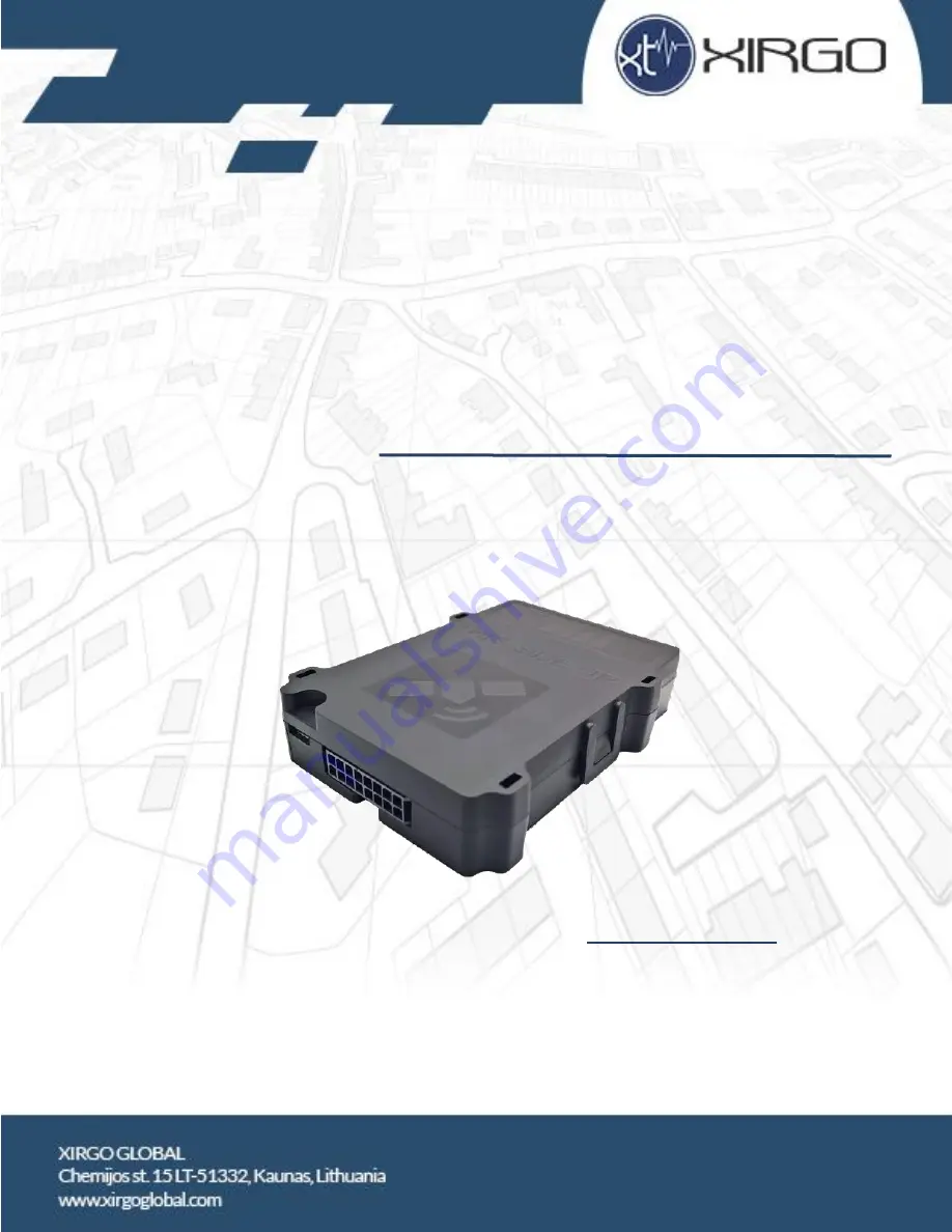
background image


FMS500 LIGHT + SDK 

GNSS VEHICLE TRACKER 


User manual 

FMS500 LIGHT+ SDK


Summary of Contents for FMS500 LIGHT+SDK

Page 1: ...FMS500 LIGHT SDK GNSS VEHICLE TRACKER User manual FMS500 LIGHT SDK ...

Page 2: ...formation 3 1 1 Safety and legal information 3 1 2 Description 3 1 3 Package 3 1 4 Technical specifications 4 1 5 Physical properties 5 1 6 Pinout diagnostic LED 7 1 6 1 Pinout 7 1 6 2 Diagnostic LED 8 1 7 Installation 9 1 8 Configuration 9 1 9 Support 10 1 10 Document versions 10 2 Annex 1 Installation instructions 11 ...

Page 3: ... data via Cellular network Digital and analog inputs of the device may be used to connect different external sensors devices Outputs of the device may be used to control external equipment remotely Flexible configuration allows users dealers to adjust the device to meet their specific requirements All device settings and firmwares are updated remotely via GPRS It is possible to create setting temp...

Page 4: ...sleep 4 mA Internal memory 8 МB Accelerometer 3 axis digital accelerometer Operational temperature range With internal Lithium battery from 20 to 60 C Without internal Lithium battery from 40 to 85 C Dimensions 68x90x19 mm Weight Tracker 64 g set 160 g Cellular and GNSS module Simcom SIM800 Ublox EVA M8M RF function EGPRS Bands Frequency GSM EDGE Bands 2 1850 1910 MHz TX 1930 1990 MHz RX GSM EDGE ...

Page 5: ...al com Physical properties Fig 1 FMS500 LIGHT SDK front view Note To insert a SIM card open the box by lifting plastic holders from both sides Table 2 FMS500 LIGHT SDK components No Short description 1 LED indicator 2 SIM card 3 Socket 2x8 pins 4 USB interface 1 2 3 4 ...

Page 6: ...Xirgo Global Chemijos st 15 LT 51332 Kaunas Lithuania www xirgoglobal com Fig 2 FMS500 LIGHT SDK dimensions mm 4 60 4 91 68 19 ...

Page 7: ...D 1 5 1 Pinout ADC5 Orange OUT1 Orange Black OUT2 White IN4 Blue black GND Black Battery Red RS232 TX Purple RS232 RX Blue OUT3 Yellow ADC5 Yellow Black 1 WIRE Brown IN5 Grey black IN3 Purple black IN2 ADC4 White black RS485 B Green RS485 A Green black Fig 3 FMS500 LIGHT SDK pinout and cable colors ...

Page 8: ...rgoglobal com 1 5 2 Diagnostic LED FMS500 LIGHT SDK has an indication LED for GNSS Cellular modem and CAN line status LED starts flashing only if IN5 digital input is connected to battery Fig 4 Cellular signal flashing example Fig 5 GNSS signal flashing example ...

Page 9: ... Modem turned on 2 Modem connected to Internet Modem GPRS registered Modem GSM registered Modem SIM card ok Modem turned on 3 Modem GPRS registered Modem GSM registered Modem SIM card ok Modem turned on 4 Modem GSM registered Modem SIM card ok Modem turned on 5 Modem SIM card ok Modem turned on 6 Modem turned on 7 Device started 1 6 Installation FMS500 LIGHT SDK is installed where risk of mechanic...

Page 10: ... easy to install device Please read and follow provided installation and operating instructions carefully However if you encounter difficulties while installing or using this product technical support is available and may be reached by e mail support xirgo com or tech_support xirgo com 1 9 Document versions Table 5 Document versions Version Date Changes 1 0 2017 07 04 Document created 2 0 2020 04 ...

Page 11: ...ybrid and electric engines where power supply specifications are met Device must be connected to the vehicle battery ensuring constant power supply even if the engine is not working and ignition is off Basic instructions before beginning the installation Quality of connections location of the device etc play a significant role on accurate operation of the system Below are some tips and rules for c...

Page 12: ... following the printed picture on the PCB insert the SIM card 3 Place the PCB to the housing and close it 4 Use plastic fastening straps to fix device in a stable position units housing has four holes for straps to go through and fasten them to the body of the vehicle 5 Connect power supply 6 Connect ignition wire to a digital input usually IN5 7 Connect array 8 Connect other devices optional Tool...

Page 13: ...the device before starting installation The device must be turned off when inserting SIM card Before inserting the SIM card make sure you have all network services activated the card s PIN code must be disabled If the vehicle is travelling to foreign countries roaming service must be activated for the SIM card The SIM card and phone number must be checked and clearly marked on the installation cer...

Page 14: ...standard glass e g without built in heating elements Fixing of the device must be stable and immobile providing for the installation durability It is necessary to take into account events which may lead to loss of device stability to select the mounting location and methods that would allow to avoid these factors Cellular antenna Cellular antenna is responsible for transfer of collected data and c...

Reviews: