background image

COLOR TELEVISION

LCD-W# 

series

LC-27W18S, LC-27W25S
LC-32W18S, LC-32W25S
LC-37W18S, LC-37W25S
LC-42W17S

Summary of Contents for LC-27W18S

Page 1: ...COLOR TELEVISION LCD W series LC 27W18S LC 27W25S LC 32W18S LC 32W25S LC 37W18S LC 37W25S LC 42W17S ...

Page 2: ...f software upgrading Working principle analysis of the unit Block diagram IC block diagram Wiring diagram Assembly list Identification criteria for the bright spot and dark spot of the LCD screen Troubleshooting Schematic diagram 1 3 10 13 14 15 19 20 22 23 34 ...

Page 3: ... will result 2 5 If any foreign substance such as water liquid metal slices or other matters happens to fall into the module be sure to cut the power off immediately and do not move anything on the module lest it should cause fire or electric shock due to contact with the high voltage or short circuit 2 6 Should there be smoke abnormal smell or sound from the module please shut the power off at on...

Page 4: ... of picture residue on the screen as commonly called ghost shadow The extent of the residual picture varies with the maker of LCD screen This phenomenon doesn t represent failure This ghost shadow may remain in the picture for a period of time several minutes But when operating it please avoid displaying still picture in high brightness for a long time 3 Points for attention during installation 3 ...

Page 5: ...e exit factory menu to press the MENU button Production of data processing board and analogue board on the line Connect to central signal source check if various TV functions station skipping modulate quantity control etc check if the output of earphone and speaker are normal White balance adjustment Input AV S signal SCART and HDTV signal check various functions under AV S terminal Input VGA sign...

Page 6: ...signal generator sends CVBS signal to the unit check if the image and sound is normal It sends image format 16 9 and 4 3 to the unit check if the unit auto identify is normal Change SCART signal to RGB signal check if the image and sound is normal It sends image format 16 9 and 4 3 to the unit check the unit auto identify is normal Select the PIP mode connect earphone cable and check if the sound ...

Page 7: ... if the image and sound is normal If the image is deflection of the H field select auto sync correction of the SCREEN menu If the image is slight disturb adjust the FINE TUNE correction of the SCREEN menu Open the PIP mode connect the earphone and check if the image and sound is normal 6 6 HDMI terminal HDMI signal format receive the three high definition signal 480P 576P 720P 50 60 Hz 1080I 50 60...

Page 8: ... 5EH 61H 61H Volume 75 64H 65H 69H 69H Volume 100 6BH 6DH 72H 72H HP VOLUME SETTING Volume 1 64H Volume 25 96H Volume 50 A1H Volume 75 AEH Volume 100 BEH MSP Scart1 Volume 72H Prescale Scart 4CH Prescale FM AM 27H Prescale Nicam 64H Scart TV Volume 20H Scart AV Volume 72H Items Ex factory setting IIC Bus off Off EEPROM Erase Off Backlight Adjustable Off Back Light 100 Menu Timeout 5 Blank switch e...

Page 9: ...00H 00H 00H 00H Sharpness Middle 10H 10H 10H 10H 10H Sharpness Max 1FH 1FH 1FH 1FH 1FH Color Min 00H 00H 00H 00H 00H Color Middle 1DH 1DH 1DH 1DH 1DH Color Max 2DH 2DH 2DH 2DH 2DH Hue Min 80H 80H 80H 80H 80H Hue Middle 20H 20H 20H 20H 20H Hue Max 7FH 7FH 7FH 7FH 7FH TABLE 6 White Balance Adjust Items LC 27WXXS LC 32WXXS LC 37WXXS LC 42WXXS R Offset 55 55 54 53 G Offset 51 53 57 49 B Offset 50 50 5...

Page 10: ...mage analog setting CVBS Vivid Standard Mild Custom Contrast 90 80 50 80 Brightness 40 35 35 35 Color 70 60 40 60 Hue 00 00 00 00 Sharpness 60 50 30 50 SC RGB Vivid Standard Mild Custom Contrast 90 85 50 85 Brightness 60 50 35 50 Color 80 65 40 65 Hue 00 00 00 00 Sharpness 60 50 30 50 YPBPR Vivid Standard Mild Custom Contrast 90 85 50 85 Brightness 50 40 35 50 Color 80 65 40 65 Hue 00 00 00 00 Sha...

Page 11: ...etting Live Pop Rock Custom 120 Hz 50 50 65 50 500 Hz 50 50 55 50 1 5 kHz 50 60 55 50 5 kHz 80 70 55 50 10 kHz 85 70 55 50 6 8 Ex factory setting of user menu 6 8 1 select TV channel 6 8 2 video menu Mode Standard NR Medium APL ON 6 8 3 sound menu Volume 20 Balance 00 Equalizer Custom HP Volume 20 6 8 4 edit menu Color System Auto Sound System DK 6 8 5 option menu Default Zoom Auto Child Lock Off ...

Page 12: ...wer switch then the screen display black screen but the indicator to blue Method 2 Enter factory menu select the IIC BUS OFF item 2 Connection upgrading tools with upgrading port 3 Dual click IAPWriter logo enter the upgrading states if the PC and the IIC communication trouble it can prompt 4 Select the file menu load the software follow as ...

Page 13: ...item of the device menu till the right screen display DONE 6 turn off the power restart the unit Note because of the software it may be no stabilization the software can auto download and write Connection cable Upgrading tools ...

Page 14: ...12 NOTE Do not shut the power off or turn the TV set on during the FLASH write Otherwise it may lead to no way for flash to rewrite Upgrading port ...

Page 15: ...tched resistance the signal send to the N506 video switch SN74CBT3257CDR via switching to selected signal EX52_Y and EX52_C to main decode IC N101 SVP EX52 video switch A D transition digital decode image scale and OSD superposition then send to LVDS level drive for LCD screen D sub and YPbPr signal thought matched resistance the signal send to the N507 video switch SN74CBT3257CDR via switching to...

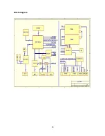
Page 16: ...14 Block diagram ...

Page 17: ... amplify then it send to speaker other way signal output left right audio send to earphone amplifier N805 NJW1109 after audio control and power amplifier it output to earphone socket Other two ways signal output audio of TV out and AV out by SCART terminal of video board MSP3410 internal block diagram as follow Main pins instructions 2 3 SCL SDA 27 28 left right audio of audio power amplification ...

Page 18: ...ecoding IC N601 TVP5147 so the PIP image of sub channel can selecting arbitrary video signal MSP3410 internal block diagram as follow TVP5147 main pins instructions 28 29 SCL SDA 22 Video input for SCART1 7 80 Y C signal input for SCART2 16 video signal input of sub tuner 8 Y signal input of AV or S Video 1 C signal input of S Video 9 2 18 YUV signal input of compatible DTV ...

Page 19: ... signal of HDMI send to N405 SiI9011 then it transform 24bit for video digital signal and sent to IC N101 SVP EX52 processing SiI9011 internal block diagram as follow 4 Main decode and processing IC DPTV SVP EX52 SVP EX52 internal block diagram as follow ...

Page 20: ...tions 14 16 SCL SDA 10 11 VGAHS VGAVS input 244 231 EX52_Y and EX52_C input 243 main tuner video signal input 242 video signal input for Scart1 226 248 233 Scart1 RGB input 246 232 225 EX52_YUV input 236 237 video output for SCART2 ...

Page 21: ...19 Wiring diagram ...

Page 22: ...n board 667 L27W18 09 LC 27W18S Button board 667 L27W18 05 LC 27W18S 667 L32W25 05 LC 27W25S Power supply board 667 L27W18 20 LC 32W18S LC 32W25S Name Part no Main IC and no Data processing board 667 L32W25 69 N101 DPTV SVP EX52 353 DPTV0 20 N201 K4D2632838F 353 26323 10 N302 W29C040P 90B 353 29040 30 N301 M30620SPGP 353 30620 20 N601 TVP5147PFP 353 51470 10 N405 SiI9011CLU 353 90110 10 N403 CS434...

Page 23: ...37W25 40 IR reception board 667 L37W18 09 LC 37W18S Button board 667 L37W18 05 LC 37W18S 667 L37W25 05 LC 37W25S Power supply board 667 L37K5 20C LC 42W17S Name Part no Main IC and no Data processing board 667 L42W17 69 N101 DPTV SVP EX52 353 DPTV0 20 N201 K4D2632838F 353 26323 10 N302 W29C040P 90B 353 29040 30 N301 M30620SPGP 353 30620 20 N601 TVP5147PFP 353 51470 10 N405 SiI9011CLU 353 90110 10 ...

Page 24: ...m 10mm 5mm Total defected point 8 7 5 4 Notes 1 Definition of defected point bright spot dark spot It is identified as a defected point if its area exceeds 1 2 of a single picture element R G B 2 Definition of bright spot It is identified as a bright spot if it is bright in the state of dark field and its bright size remains unchanged 3 Definition of dark spot It is identified as a dark spot if it...

Page 25: ...nd if interfered possibly by the equipment like transmitting antenna non professional radio station and cellular phone 1 2 TV set Symptoms Possible cause Unable to switch the power on Check to see if the power plug has been inserted properly into the socket No picture and sound Check to see if the power supply of liquid crystal TV has been switched on As can be indicated by the red LED at the fron...

Page 26: ... batteries are installed in the reverse order Check if the battery is effective Check the distance or angle from the monitor Check if there is any obstruct between the remote control and the TV set Check if the remote control signal receiving window is exposed to strong fluorescence No picture and sound but only hash Check if the antenna cable is correctly connected or if it has received the video...

Page 27: ...mal Check the signal inputted from the channel to pin IC is normal or IC and its periphery is normal or the output of LVDS is normal Check if the display of each channel s audio signal is normal Check the signal inputted from the channel to pin IC is normal or IC TPA3008D2 MSP3410 and its periphery is normal No raster no picture and no sound Check Standby5V Is the blue indicator lights Disconnect ...

Page 28: ... that one of N301 N302 or N303 fails to work properly probably is N302 If R110 and R111connects N301 with N101fails to work will also lead to the failure phenomenon 2 No picture but with sound blue screen and OSD appear Yes No Yes No NOTE Please refer to checking procedure 5 to get the methods for checking the phenomenon of no picture but with sound of HDMI channel Check N301 and its reset circuit...

Page 29: ...t Speaker fails to work Check if correspondent pins of power amplifier have output Sound only with raster Check if the power supply of LVDS is normal or not Check the signal outputted from N101 to X189 is normal or not The receiving board of LVDS fails to work properly Check the power supply and the periphery circuit of N101 Check pin 5 of N705 or pin 2 and 4 of N715 is low level or not Check the ...

Page 30: ...input signal Check periphery circuit of N801 crystal oscillation and power supply circuit Follow the direction of audio signal input to check each channel Check if C164 has input signal Check if pin 2 of N506 has input signal Check if C164 and C165 have input signal Check periphery circuit of N101 crystal oscillation and power supply circuit There exits problems at the place from socket of AV term...

Page 31: ...ck the circuit between TUNER201 and N101 Check periphery circuit of TUNER201 power supply circuit and bus Check if pin 12 of TUNER202 has output signal Check if the horizontal and vertical synchronous signal clock signal outputted from N601 are normal or not Check if pin 16 of N601 has input signal There exits problems at the place from socket of S terminal to N506 Check periphery circuit of N506 ...

Page 32: ...wer supply Measure whether there is signal input to C162 C183 C184 C185 There is trouble at the path from SCART1 socket to N101 Measure whether there is signal input to C164 C165 Check whether the connection between SCART1 socket pin 16 and X807 pin 9 is normal Switch the signal between SCART1 RGB and VIDEO input measure N301 pin 87 to check whether there is level change The trouble is at Resistor...

Page 33: ...path from N507 output to N101 input Check N507 surrounding circuit and power supply There is trouble at the path between YpbPr socket and N507 Input YpbPr signal and check whether the display is normal Check N101 surrounding circuit crystal oscillation and power supply Measure and check whether there is signal input to N506 pin 3 and pin 6 There is trouble at the path from SCART2 socket to N506 Ch...

Page 34: ...ion to HDMI socket is well going Measure whether N101 pin10 pin 11 have Sync signal input There is trouble at the path between VGA socket and N507 Measure whether there is sync signal input to N501 pin 1 and pin 5 Check N501 surrounding circuit and power supply There is trouble at the path between VGA socket and N501 Check N101 surrounding circuit crystal oscillation and power supply Check and mea...

Page 35: ...pin 1 pin 12 have signal input Check N581 surrounding circuit and power supply Check whether N403 pin7 and pin10 have output signal Check the path between N403 and N581 Check whether N403 pin1 2 3 4 have input Check N403 surrounding circuit and power supply Check according to procedure h ...

Page 36: ...34 Schematic diagram ...

Page 37: ......

Page 38: ......

Page 39: ......

Page 40: ......

Page 41: ......

Page 42: ......

Page 43: ......

Page 44: ......

Page 45: ......

Page 46: ......

Page 47: ......

Page 48: ......

Page 49: ......

Page 50: ......

Page 51: ......

Page 52: ......

Reviews: