Summary of Contents for VESDA

Page 1: ...VESDA Accessories Guide www acornfiresecurity com www acornfiresecurity com...

Page 2: ...le and cannot be held accountable for any liability that may arise due to improper use of the equipment and or failure to take proper precautions Only persons trained through an Xtralis accredited tra...

Page 3: ...he following icons are used in this document Convention Description Caution This icon is used to indicate that there is a danger to equipment The danger could be loss of data physical damage or perman...

Page 4: ...ch is on a different power circuit to the receiver or consult the dealer or an experienced radio television technician for help FDA This Xtralis product incorporates a laser device and is classified a...

Page 5: ...3 1 Remote Box 7 3 2 19 Subrack 9 3 3 Wiring Remote Systems 11 4 The Modules 15 4 1 The Display Module 15 4 2 LCD Programmer 17 4 3 VESDAnet Socket Module 18 4 4 Remote Termination Card 20 4 5 System...

Page 6: ...he reader with instructions on installing and cabling the respective modules The VESDA Accessories Product Guide is written for those people who are involved with the design specifications maintenance...

Page 7: ...plement VESDA detectors The modules available for remote mounting are l The display module l The LCD programmer module l VESDAnet socket module l 7 and 12 relay remote termination cards and relay proc...

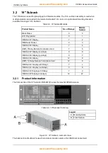
Page 8: ...No of Relays Product Code Remote Programmer Unit 0 VRT 100 Remote VESDA VLP Display Unit 7 VRT 200 VESDA VLP Remote Display Without Relays 0 VRT 600 Remote VESDA VLS Display Unit 7 VRT 400 Remote VESD...

Page 9: ...ny flat surface To mount the remote box first unscrew the front cover Then use the four screw holes to secure the mounting box onto a flat surface ensuring that it is horizontally straight Connect the...

Page 10: ...7 4 DRP 7 Relay Remote Termination Card 7 5 VESDA VLP Display no relays 0 6 VESDA VLS Display no relays 0 7 VESDA VLS Display 12 8 DRP 12 Relay Remote Termination Card 12 9 VESDA VLC Display with Rela...

Page 11: ...four holes in the dividing panel of the 19 Subrack for wiring between the front and the back VESDAnet and power connections are installed by default in the factory 3 2 4 Installing Modules The 19 Subr...

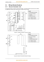
Page 12: ...ower supply terminals relays and relay terminals Legend A VESDAnet Terminals B Power Terminals C Relays D Relay Terminals E 10 Way Connector F5 11 Way Connector Figure 3 5 Remote Termination Card with...

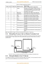
Page 13: ...7 An example of the wire connection for VESDAnet Closed Loop Relays The relays interface with auxiliary external items such as loop interface modules beacons or sounders These may also be interfaced w...

Page 14: ...3 Energizes when the First Alarm Sector 3 has been identified 11 First Alarm Sector 4 Energizes when the First Alarm Sector 4 has been identified 12 Scan Energizes when the Scanner is scanning the in...

Page 15: ...and can only be inserted one way into a socket Do not attempt to force a connector into its socket If there is any difficulty reverse the orientation of the connector before inserting again 3 3 5 Back...

Page 16: ...ination card l LEDs and Buttons The Threshold Indicators provide at a glance the visual representation of the programmable alarm thresholds The Bar Graph continuously displays the current level of det...

Page 17: ...gree viewing a Push Button Keys Mode Test Silence Scan Reset Isolate Can be disabled during commissioning except Silence Fault Indicators System Power Airflow VESDA Address also called Zones Network F...

Page 18: ...nance of the VESDA system It is used to program and maintain the detector The LCD Programmer Module can be mounted into a detector remote box or a 19 Subrack It is also available as a Handheld model F...

Page 19: ...VESDAnet using the VESDAnet Socket A VESDAnet socket is located on the detector termination card of VESDAnet capable detectors However the VESDAnet Socket Module can be mounted onto a remote box or a...

Page 20: ...on the VESDAnet socket card enable VESDAnet communication wires to be brought into the VESDAnet socket module and looped out to another device Data communication on VESDAnet is bidirectional The polar...

Page 21: ...Card 4 4 1 Features of Remote Termination Card l 7 programmable relays or 12 relays for VLS l The default values for the relays correspond to respective default values for 7 and 12 Relay Head terminat...

Page 22: ...n x 26 mm 1 02 in Dimensions in Remote Mounting Unit 140 mm 5 5 in x 150 mm 5 9 in x 85 mm 3 4 in Operating Temp 0 to 39 C 32 F to 103 F Humidity 10 99 RH non condensing 4 4 4 Mounting the Remote Term...

Page 23: ...o called Zones on the VESDAnet loop l 7 programmable relays l Can be wired to a secondary reporting device e g a sounder or a beacon l Option for recessed mounting l Programmable with Xtralis VSC l In...

Page 24: ...tector Ver 3 07 05 and later High Level Interface HLI Ver 3 05 04 and later LCD Programmer Ver 3 02 1 and later denotes language The LCD Programmer cannot configure the system relay module Displays do...

Page 25: ...the center to fit around the miniature sampling points Sampling point decal This decal is wrapped around a pipe on the sampling hole The decal has a hole in the center The hole in the decal must be a...

Page 26: ...cal 25 polarity 19 power source 14 programmed relays 12 push button keys 15 R relay processor card 13 relays 12 remote box 7 8 remote display unit 7 remote mounting 7 remote programmer unit 7 remote s...

Reviews: