background image

Ai

1  

All-in-one, rugged, remote monitoring 


Product Manual 


Oct-22 Revision 


Summary of Contents for Ai1 Series

Page 1: ...Ai1 All in one rugged remote monitoring Product Manual Oct 22 Revision...

Page 2: ...ails THE MANUFACTURER EXPRESSLY DISCLAIMS AND EXCLUDES ANY IMPLIED WARRANTIES OF MERCHANTABILITY OR FITNESS FOR A PARTICULAR PURPOSE The Manufacturer hereby disclaims to the fullest extent allowed by...

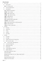
Page 3: ...rnal barometer 11 4TO20 4 to 20mA output option 11 2 Ai1BUOY 12 2 1 Unboxing 12 2 2 Dimensions 12 2 3 Wiring 13 2 4 USB Port 14 2 5 Gland Plate 15 3 Ai1POLE 17 3 1 Unpacking 17 3 2 Mounting 17 3 3 Ai1...

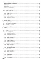
Page 4: ...Option mounting plate 37 5 4 Ai1BUOY Bird Spike Kit 37 6 Training 38 7 Sensor Specific Considerations 39 7 1 Wiring 39 7 2 Water Quality Sondes 39 7 2 1 Eagle io Configuration 39 7 2 2 Hydrosphere Con...

Page 5: ...3 7 10 5 Barometric pressure correction 54 7 11 RadarLEVEL or UltraLEVEL 54 7 12 All In One Weather Sensors 55 7 13 Thermistor Chain 56 8 Communications 57 8 1 USB Radio Modem RADUSB 57 8 2 Radio Base...

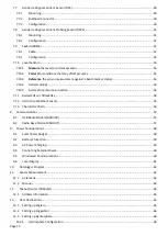
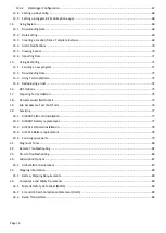
Page 6: ...74 17 Preparing for Installation 75 18 Recommended field tool kit 75 19 Site Acceptance Test SAT Form 76 20 Servicing 77 20 1 Ai1BUOY SIM card installation 77 20 2 Ai1BUOY Battery replacement 77 20 3...

Page 7: ...ng power communications and integrated sensors and output modules 1 1 Power options Ai1BUOY 27W 3 x 9W solar panels Suits buoy platforms where the platform is free to move and rotate Uses internal 6Ah...

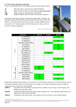
Page 8: ...Hz Yes Yes B2 1900MHz Yes B3 1800MHz B4 AWS 1700 2100MHz B5 850MHz Yes Yes B6 800MHz Yes B8 900MHz Yes Yes Along with the primary communication a local network or local control can also be used For th...

Page 9: ...O utilization for each option and confirms that the Ai1 has capacity Figure 2 Iridium Quick Start guide Iridium Technical Specification The Iridium SBD transceiver provides true global operation with...

Page 10: ...OLE via the M12 universal wiring system The display for the Ai1POLE is typically mounted at eye level on the same pole as the Ai1 The display includes a waterproof button for program control A short p...

Page 11: ...the SWITCH RELAY or LATCH power switching options The pump operates at up to 500mL min flow rates SOA EXO Signal Output Adapter SOA Integrated inside the Ai1 with 4 wire connection using the Custom te...

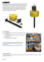
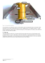
Page 12: ...nt weighs approximately 32kg 2 1 Unboxing When removing from the box take care to keep the packet of parts supplied with the station which include 1 Bird spike kit 2 Toolkit AC plug pack USB cable spa...

Page 13: ...clear electronics plates 2 3 Wiring The wiring and control of the Ai1 is via the terminal plate at the bottom of the system protected behind a clear acrylic plate with an o ring seal Cable entry can b...

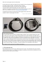
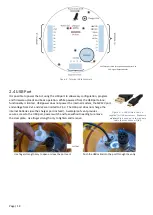
Page 14: ...t does not charge the internal batteries use the charger port instead A waterproof vent provides secure access to the USB port power switch and fuse without needing to remove the clear plate Use finge...

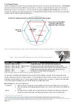
Page 15: ...ve4 It is not possible to add a 3rd Micro circular connector due to the bulkhead connector height so if a 3rd sensor using the Micro circular system is required a Y cable is recommended or consider us...

Page 16: ...into this hole for manual activation of measurements or data transmission while on site to confirm the site operates correctly This is best paired with the internal display option Glands The 15 8mm 5...

Page 17: ...3 3 Ai1POLE and Ai1 EXT mounting options The Ai1POLE Ai1 EXT and associated displays and accessories suit either 32NB Nominal Bore 40NB or 50NB pipe which is available in galvanised steel or stainles...

Page 18: ...SPOST2 Permanent A taller post ideally suited to all in one weather stations The 1 8m post elevates weather sensors to 2 0m a widely accepted exposure standard such as the American Association of Stat...

Page 19: ...wo sensors into a single port the Y cable has two female connections for connecting to any of the above cables while connecting into the Ai1 bulkhead connector The Y cable suits compatible sensors suc...

Page 20: ...a predrilled port on the side of the Ai1 For extension cables the connector gender is as described in the schematic here It is possible to order an additional M12 sensor connector for adding a second...

Page 21: ...e the supplied two part epoxy to eliminate any potential moisture build up and provide additional mechanical strength5 3 5 Universal Wiring System The Ai1POLE has standardized the wiring for connectin...

Page 22: ...n be either C1 Tx or RS485_B depending on the solder jumpers selected and 2RA is a similar multi function terminal that can be C2 Rx or RS485_A The solder jumpers are aligned behind to terminals as sh...

Page 23: ...1 2 Starflow QSD red cable SW12V C1 GND Port 1 2 Starflow QSD brown cable SW12V C1 GND Port 1 2 Strobe light SW12V GND Port 1 2 Sampler activation SW12V GND Port 1 2 Data Display Vx2 C1 A1 GND PSW Por...

Page 24: ...sing using either the cable clip or conduit clip option to protect the cable Any exposed cable may be protected with spiral cable wrap This is the same location recommended for Flexicon or similar rug...

Page 25: ...ection 1 Red SW12 or BAT X 1 Brown NO 2 Black GND X 2 White NO 3 Yellow Enable SE1 6 Typ A1 X 3 Blue COM 4 Green Not used 4 Black COM 5 Blue Not used 5 Grey NC uses Analog main board header Regulated...

Page 26: ...Output module Provides a HART compatible 4 20mA output signal controlled using the dataloggers RS232 port A CRBasic library is provided for serial communications to the interface FUTURE RS232 to UART...

Page 27: ...i1POLE https youtu be XM7uw8rlSbU 3 11 Ai1POLE Bird Spike Kit The Ai1POLE bird spike kit is supplied for final assembly on site The kit includes two parts A long bird spike strip to be mounted on the...

Page 28: ...Page 28 Correct parallel spike installed first Incorrect perpendicular spike installed first...

Page 29: ...t depends on the program which is supplied to suit the sensors ordered The tables always include Ai1 logged status and diagnostic information DataTableInfo how much data is stored in each table ErrorL...

Page 30: ...k on ReadNow set it to non zero i e 1 and the program will measure the connected sensors Scroll down to view the Measurements section Refer to Sensor Specific Considerations in section 7 for details o...

Page 31: ...dem will be off Excitation ports limited to 2 5V rather than 5V Switched 12V will not operate Single flash every 15 seconds Operating on battery solar power Full system functionality Always on Program...

Page 32: ...ble 6 below for details of internal sensor options This port is limited to 2 5V when powered from USB The voltage of the excitation port is controlled with a 12 bit DAC from 150mV to 5000mV Vx2 Switch...

Page 33: ...from 200mV to 5000mV G System ground used for power ground or analog reference The excitation port powers the common internal sensor options such as internal humidity operating current and GPS These c...

Page 34: ...on C and Normally Open outputs For example a relay connected to A3 input has the common terminal wired to A3 and the normally open terminal wired to A3 Similarly the relay connected to A4 has its own...

Page 35: ...h is viewed from the Current_mA public variable Charging current i e when the solar panels are in sunlight will be negative while discharging current i e sensors or communications active in high curre...

Page 36: ...using a lantern it is turned OFF for shipping to prevent battery discharging The lantern must be turned on prior to mounting on the top of the Ai1 Open the waterproof cover on the underside of the lan...

Page 37: ...r mounting the spikes Refer to Figure 20 for the M3 screws mounting the spikes along the top of each panel Earlier spring steel bird spike kit The bird spike kit is fitted on the top of the Ai1 using...

Page 38: ...kip to Public variables in the next video unless you want to write your own program 4 Send a program collect and view data 3 30 Connect 0 17 Send a program 0 41 Public variables 1 32 Collect data 2 17...

Page 39: ...t a wide variety of data with various measurement units using SDI12 It is possible to detail the sequence of these parameters and their measurements units at each stage in the program or to treat the...

Page 40: ...tab to describe the measurement units used i e C Click Save and repeat for other parameters Highlight the Ai1 select Parameters from the views and review that the names and units are correct 7 2 2 Hy...

Page 41: ...s memory while also sending data to the Ai1 If the Ai1 fails for any reason the sonde will continue operation with the data available for manual download When using an EXO sonde with the RS485 interfa...

Page 42: ...A Sonde Wiring Color Orange Black Red Yellow White Ai1 Wiring EXO with RS485 or SOA Disconnect BLACK term U3 RED term U4 YELLOW term U1 WHITE term U2 EXO3 SDI12 natively C1 G 12V SW12V The red wire m...

Page 43: ...s and their sequence as below The measurements for the sonde are displayed in the Public table viewed from the Data Monitor tab The Ai1 does not know the name of each parameter or their units but disp...

Page 44: ...re data was downloaded from the Ai1 the sonde record will always be available It is also recommended to set Sample and Hold to true so that the measurements are the same and quick responses are provid...

Page 45: ...n Hydrosphere If the values are to be mapped to Hydrosphere see section 13 3 the internal display or other destination the correct public variable name must be used These names are aliases to the arra...

Page 46: ...d A to BAT or SW12V Green C to GND White D to RS485_B Black E to RS485_A Refer to Table 3 on page 22 for details on the wiring inside the Ai1 The bulkhead requires a 17 5mm hole gasket and backing nut...

Page 47: ...lled wiping The ZebraTech control unit is added into the Ai1 when selecting the WIPER option The wiper can only be added to the Ai1POLE version not the BUOY version due to the wiper having insufficien...

Page 48: ...ect the cables to the IQ Serial Adapter as shown below 7 6 2 Sensor Cable M12 Pin Std color IQ Cable Sensor End Pin Colors Pin 1 Brown Red Pin 2 White White Pin 3 Blue Orange Pin 4 Black Black Pin 5 G...

Page 49: ...the cable into the tube using cable ties along the way 7 7 2 Bulkhead Connector As with the EXO sonde the DCS being a common option is supplied with a bulkhead connector prewired Refer to the CRBasic...

Page 50: ...RESET Run the sensor with the new settings The DCS does not have a function to reset to factory defaults so it is best to check each configuration parameter listed above for correct values For a list...

Page 51: ...urther off from the instrument tube is required different to the DCS bracket 7 8 2 Configuration The DCPS operation is almost identical to the DCPS except that the default baud rate is 115 200 The int...

Page 52: ...2 Configuration The main setting to confirm is OutputFormat 3 engineering units in decimal as compared to raw and in hex The Seabird can not be in autonomous mode or it will fail to respond to pollin...

Page 53: ...easurement against a benchmark or datum LevelSensor measurements are relative to the installed elevation and must normally be referenced to a local or global benchmark commonly a cease to flow elevati...

Page 54: ...L have a beam spread of 8 half angle or off center While the UltraLEVEL has filtering to reduce readings from small objects within the beam best results are obtained with a clear view to the water sur...

Page 55: ...curacy Range Accuracy Wind Speed 0 40m s 0 3m s 3 0 30m s 0 3m s 3 0 60m s 3 Wind Direction 0 360 3 0 360 5 0 360 3 Air Temperature 50 to 60 C 0 6 C 50 to 60 C 0 3 C Rel Humidity 0 to 100 3 0 to 100 3...

Page 56: ...e the tube 3 Most applications require the thermistor chain to hang free from the buoy for correct depth spacing Alternatively the thermistor may be cable tied to the mooring line depending on project...

Page 57: ...in a weatherproof enclosure designed for pole mounting The RADOUT includes two U bolts suitable for poles from 38mm to 65mm in diameter At the bottom of the radio is an M12 connector The RADOUT includ...

Page 58: ...W panel with 45 fixed mounting towards winter sun 9W Ai1POLE 17W panel with 45 fixed mounting towards winter sun 17W Ai1BUOY 2 x 9W panels with 45 angle mounting on buoy 11W Ai1BUOY 3 x 9W panels vert...

Page 59: ...sages and Errors and ErrorLog data table will display information relating to the battery protection if activated It is important to ensure the Ai1 is turned off when in storage used in an area suitab...

Page 60: ...housing and follow the steps up to pulling out the battery cable When using external power ensure LOW_BATTERY_SAVER_V and LOW_BATTERY_SHUTDOWN_V are configured sensibly for the battery type i e Lead A...

Page 61: ...Current Humidity Can be changed to Vx1 if RS485 adapter is not used DISPLAY_INTERRUPT_POWER_PORT P_SW Provides excitation power to switch DISPLAY_INTERRUPT_PORT SE1 Used to activate display as soon a...

Page 62: ...agreement As the software is in rapid development the OS features will continue to be enhanced The testing with a new OS library file is up to the end user to ensure compatibility with the Ai1 hardwa...

Page 63: ...is the recommended scan rate for optimum balance of responsiveness and current efficiency 11 2 Manual It is also possible to trigger manual measurements or control sensor power by setting program var...

Page 64: ...these for you If you are unsure of the configuration and have lost your shipping documents connect directly to the Ai1 using the USB port and you can read the settings direct from the unit except TCP...

Page 65: ...data storage may result in higher data transfer The exact steps depend for each destination option depends on the application software several are illustrated using the most common applications Eagle...

Page 66: ...y Saver threshold value i e 12 75V and the category Several alarms i e Battery and Internal Humidity are configured in the template while measurement alarms are specific to the station 13 2 Setting up...

Page 67: ...string that now appears under Login Id i e IfKlE 1DBHx M1qSf BBFig in this instance 13 3 2 Datalogger Configuration The program configuration related to Hydrosphere is in two parts The HYDROSPHERE_ID...

Page 68: ...er providing the networking Full instructions for configuring LoggerLink can be found in section 4 Set up LoggerLink in this manual https s campbellsci com documents eu manuals premium konect pakbus r...

Page 69: ...y need to be removed from the historic data set due to site issues such as having the sonde out of the water during cleaning Eagle io makes this easy The most common way to identify a problem is to lo...

Page 70: ...4 4 Alarm Notifications Once an alarm is configured i e Battery Voltage or Internal Humidity alarms described in section 13 1 or an alarm from a measurement such as Turbidity it is possible to subscri...

Page 71: ...fig exe 15 1 Sending a new program A connection to the station can be established remotely using PBRouter or locally with a USB cable plugged into the port at the bottom of the unit Using DevConfig se...

Page 72: ...t can be recharged in an oven at 105 C for three or four hours Refer to section 4 1 5 under Humidity for steps to check the state of the desiccant Check the internal battery voltage If the Ai1 has acc...

Page 73: ...atus table find the variable FullMemReset and enter the code 98765 Once entered listen for the sounds of the logger resetting Follow the steps under 15 1 for sending the retrieved program back to the...

Page 74: ...n Time GMT 0 UTCDate Date in the format YYMMDD where DD is the Day of the Month 1 to 31 MM is the Month 1 to 12 and YY is the first two digits of the Year referenced to UTC Latitude Longitude Latitude...

Page 75: ...be 13V or higher Turn off if not installing immediately after FAT 11 Inspect o ring making sure it is clean and sealing correctly Replace if damaged32 12 When closing the bottom plate ensure that cab...

Page 76: ...eryShutdown _____ V GPS fitted GPS No GPS Location Latitude ___________________ Longitude ___________________ Reporting to Eagle io Pakbus Router Other ______________ Communications online Yes CellRSS...

Page 77: ...l the SIM card until feeling it click securely into position Reverse the steps to reassemble the housing If not already configured follow the steps to configure the APN 20 2 Ai1BUOY Battery replacemen...

Page 78: ...out completely for a better view 20 4 Ai1POLE Battery replacement The battery can be replaced by cutting the cable tie holding the battery in position and disconnecting from the lead to the Ai1 as sho...

Page 79: ...table provides the replacement specifications as well as a link to McMaster Carr for ordering individual parts Use Description click link for McMaster Carr supply Top plate o ring seal M6 1mm pitch x...

Page 80: ...tch the status of various operations or interact with serial sensors using terminal mode on the datalogger It is recommended to use DevConfig instead of LoggerNet connect for datalogger terminal conne...

Page 81: ...In this example the instrument 013YSIIWQSGEXOSND100 responds a YSI EXO sonde The exact format of this response is manufacturer specific Type 0M This initiates a measurement The response is of the form...

Page 82: ...InternalHumidity Internal Humidity will slowly increase over time especially when the Ai1 is opened to access the USB port When the desiccant is completely consumed night time condensation may occur w...

Page 83: ...r remote support has been active for a long time then the station may need a higher data plan cap Pre paid SIM cards commonly run out of credit causing an abrupt stop Refer to the service provider for...

Page 84: ...Make sure that the fuse is installed and not blown The fuse has two small tabs on the top that allow measurement of continuity without removing from the holder e If you have a multimeter and are compe...

Page 85: ...e settings vary depending on your service provider For a Global SIM card issued from the factory the APN is super or wireless twilio com depending on the model refer to the shipping documentation or t...

Page 86: ...n click the End Export button 8 Ai1 Data Table The Ai1 records important diagnostic details every SLOW_MEASUREMENT_INTERVAL typically every 15 to 60 minutes This includes information such as battery v...

Page 87: ...p to 25MB month station typically included in the Eagle io subscription36 The Global SIM will automatically connect to the best available network which can be seen from the Deployment Cellular tab und...

Page 88: ...cessfully connected Operator Switching back to Settings Editor Cellular switch Cell List Network Operators back to Disabled and enter the Operator ID to use under Cell Network Operator ID as shown bel...

Page 89: ...the Ai1 by air confirm with your airline specifically38 Figure 44 An example of the Delta airline requirements at the time of reference is shown here The Ai1 battery has four internal cells each with...

Page 90: ...on request The Iridium SBD module uses an 9602N transceiver with various regional certifications Download from https www iridium com products iridium 9602 Includes RoHS REACH EU Declaration of conform...

Page 91: ...n The object of the declaration described above is in conformity with Directive 2011 65 EU of the European Parliament and of the Council of 8 June 2011 on the restriction of the use of certain hazardo...

Page 92: ...ta adequate maintenance and investigation of alarm and diagnostic information Stations are designed to be mounted above maximum flood elevation flooding may result in damage To protect the design info...

Reviews: