background image

Installation, Operation 

and Maintenance Manual


e-SV 

S

eries

Multistage Vertical Pump Unit 

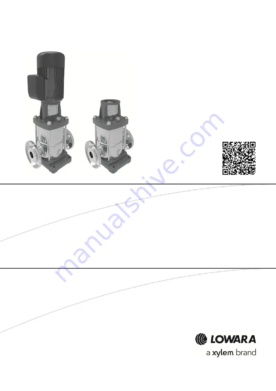
Summary of Contents for LOWARA e-SV Series

Page 1: ...Installation Operation and Maintenance Manual e SV Series Multistage Vertical Pump Unit...

Page 2: ...n components 14 3 4 Intended use 14 3 5 Improper use 15 3 6 Use in water distribution networks for human consumption 15 3 7 Special applications 16 4 Installation 17 4 1 Precautions 17 4 2 Mechanical...

Page 3: ...al overload protection triggers 34 7 6 The unit runs but there is little or no flow rate 34 7 7 When switched off the unit turns in the opposite direction 35 7 8 The unit produces excessive noise and...

Page 4: ...inal instructions 4 e SV series Installation Operation and Maintenance Manual 10 2 EU Conformity Declaration n EMCD08 43 10 3 Pump EC Declaration of Conformity Original 44 11 Warranty 45 11 1 Informat...

Page 5: ...may be supplied with supplementary instruction manuals For situations not considered in the manual or in the sales document contact Xylem or the Authorised Distributor 1 2 Safety 1 2 1 Danger levels...

Page 6: ...be carried out by children without supervision WARNING For countries outside the EU this product is not intended for use by persons including children with reduced physical sensory or mental capabilit...

Page 7: ...n and storage to prevent contamination from external substances Depending on the model the Manufacturer delivers the unit and its components in 1 A cardboard box or 2 A cardboard box with wooden base...

Page 8: ...r cutting the straps if fitted 3 Check the unit for integrity and to make sure that there are no missing components 4 In case of damage or missing components promptly contact Xylem or the Authorised D...

Page 9: ...handling the unit The eyebolts screwed on the motor must only be used to move the unit upright from its horizontal position on the ground and only for as long as strictly necessary See the figure belo...

Page 10: ...Follow the same instructions for the storage of the packed unit 2 Empty the unit by removing the drain plug This operation is essential in exceptionally cold environments any residual liquid in the un...

Page 11: ...nit details Identification code Figure 5 Data plate Position number Description Position number Description 1 Pump or pump unit type 8 Flow rate range 2 Pump or pump unit code 9 Head range 3 Mechanica...

Page 12: ...F N R H high temperature 150 C round flanges PN 25 versions F N B high temperature 180 C round flanges PN 25 version N E passivated and electropolished versions N V C K P W high temperature 150 and lo...

Page 13: ...N E passivated and electropolished version N W high temperature 150 and low NPSH versions G N Y high temperature 180 and low NPSH version N U passivated electropolished and low NPSH version N I high t...

Page 14: ...8 Motor 3 4 Intended use Pressure boosting and water supply systems Washing and cleaning sector including washing of vehicles Circulation of hot and cold liquids for example water or water glycol for...

Page 15: ...than water for example wine or milk Pumping liquids containing abrasive solid or fibrous substances Using the unit for flow rates exceeding the flow rate indicated in the data plate Examples of improp...

Page 16: ...he following cases If liquids with a density and or viscosity value exceeding that of water such as water and glycol mixture must be pumped If the pumped liquid is chemically treated for example softe...

Page 17: ...ivate aqueduct or to a well for the supply of water for human and or animal consumption WARNING It is prohibited to pump drinking water after use with other fluids WARNING Remove the unit from its pac...

Page 18: ...e must have a compression resistance of C12 15 and meet the requirements of exposure class XC1 according to EN 206 1 Sizes must be appropriate for the sizes of the unit support plate See the section F...

Page 19: ...Vibration reduction and the Hydraulic connection sections 4 2 5 Reducing vibrations The motor and the flow of liquids in the pipes may cause vibrations which can be exacerbated by incorrect installat...

Page 20: ...rt the pipes independently to prevent them from weighing on the unit 5 To reduce the transmission of vibrations between the unit and the system and vice versa install anti vibration joints on the suct...

Page 21: ...n the level is at the minimum 12 In case of suction lift installation the suction pipe must have an increasing slope towards the unit exceeding 2 to avoid air pockets also install A foot check valve t...

Page 22: ...ection conductor ground to the ground terminal before attempting to make any other electrical connections DANGER Electrical hazard Connect all the electrical accessories of the pump unit and motor to...

Page 23: ...nk or basin 4 When thermal relays are used the type sensitive to phase failure is recommended 4 4 4 Motor guidelines If using a motor other than the standard motor check that a thermal protection devi...

Page 24: ...Bolt size Torque 71 80 M6 6 53 90 100 112 M8 15 133 132 M12 50 443 160 180 200 225 250 M16 75 664 Electrical connection of the motor 1 Open the terminal box cover 2 Connect the power supply conductors...

Page 25: ...erter for speed control The converter exposes the insulation of the motor to a greater load determined by the length of the connecting cable observe the requirements of the Manufacturer of the frequen...

Page 26: ...after it has cooled down risk of physical injury WARNING Hot surface hazard Be aware of the extreme heat generated by the unit WARNING It is prohibited to put combustible materials near the unit NOTIC...

Page 27: ...ecessary loosen the plug further D 5 Tighten the plug C 6 Tighten the plug D 7 Open both the on off valves slowly and fully Models 10 15 22 33 46 66 92 and 125SV 1 Close the on off valves on the sucti...

Page 28: ...fully open the on off valve on the discharge side Figure 16 Suction lift installation priming 5 3 Checking the direction of rotation three phase motors Before starting the pump unit NOTICE Check that...

Page 29: ...ut off the discharge on off valve almost completely 3 Fully open the suction on off valve 4 Start the unit 5 Gradually open the discharge on off valve until half open 6 Wait a few minutes and then ful...

Page 30: ...time or immediately after the seal is replaced more liquid may temporarily leak out To help the seal settle and to reduce leaking 1 Close and open the on off valve on the discharge side two or three t...

Page 31: ...it at least 10 minutes for the residual current to dissipate 6 2 Maintenance every 4000 hours of operation or every year When the first of the two limits is reached 1 Measure the pressure at zero flow...

Page 32: ...M8 G 3 8 35 310 30 265 20 177 25 220 33 46 66 92SV M12 M16 M6 M10 G 1 2 R 3 8 M16 60 530 60 530 8 71 35 310 40 354 40 354 40 354 125SV M12 M16 M6 M10 G 1 2 R 3 8 M16 M10 M10 65 575 60 530 8 71 35 310...

Page 33: ...estore the power supply The thermal overload protection of the motor has been triggered Reset the thermal overload protection on the control panel or the unit The device that detects the absence of li...

Page 34: ...brated at a value too low in relation to the rated current of the motor Recalibrate Input voltage outside the rated limits Make sure the voltage values are correct Unbalanced input voltage Make sure t...

Page 35: ...bubbles in the suction pipe or in the unit Repeat the priming procedure Check valve locked in closed or partially closed position Replace the check valve Foot check valve locked in closed or partiall...

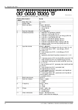
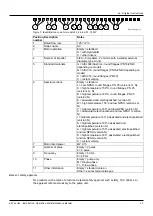
Page 36: ...en Original instructions 36 e SV series Installation Operation and Maintenance Manual...

Page 37: ...ue to chemical incompatibility with the liquid Replace the mechanical seal with one of a make chemically compatible with the pumped liquid 7 12 The motor becomes excessively hot Cause Remedy Room temp...

Page 38: ...Xylem or the Authorised Distributor Elevation 1000 m 3280 ft above sea level NOTICE If the unit is installed at an altitude greater than the stated one reduce the power output of the motor according...

Page 39: ...operating pressure PN NOTE The formula applies to units with motor with axially locked bearing on the drive side standard Xylem Figure 20 Pressure diagram 8 4 Maximum number of starts per hour Motor...

Page 40: ...220 230 6 3 3 1 220 380 5 380 660 10 8 8 Noise level Measured in free field at a distance of one metre from the unit with standard Xylem motor operating without load 50 Hz motors Table 6 LpA noise lev...

Page 41: ...l Materials 1 3 5 10 15 22 Stainless steel 33 46 66 92 125 Stainless steel cast iron 8 10 Mechanical seal Model Motor power kW Rated diameter mm in Balance d Rotatio n Version according to EN 12756 1...

Page 42: ...Disposal 9 1 Precautions WARNING The unit must be disposed of through approved companies specialised in the identification of different types of materials steel copper plastic etc WARNING It is prohib...

Page 43: ...ggiore 20 10 2017 Amedeo Valente Director of Engineering and R D rev 00 10 2 EU Conformity Declaration n EMCD08 1 Apparatus model Product see label on SAFETY manual 2 Name and address of the manufactu...

Page 44: ...nual fulfils the relevant provisions of the following European Directives 2006 42 EC Machines ATTACHMENT II physical or legal person authorised to compiling the technical folder Xylem Service Italia S...

Page 45: ...en Original instructions e SV series Installation Operation and Maintenance Manual 45 11 Warranty 11 1 Information For information on the warranty refer to the documentation of the sale contract...

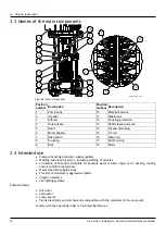
Page 46: ...en Original instructions 46 e SV series Installation Operation and Maintenance Manual...

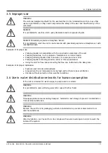
Page 47: ...en Original instructions e SV series Installation Operation and Maintenance Manual 47...

Page 48: ...ing services settings Xylem also provides a leading portfolio of smart metering network technologies and advanced analytics solutions for water electric and gas utilities In more than 150 countries we...

Reviews: