background image

PSE-800-M Low Water Cut-off

Installation,

Operation, and

Maintenance Manual

Summary of Contents for McDonnell & Miller PSE-800-M

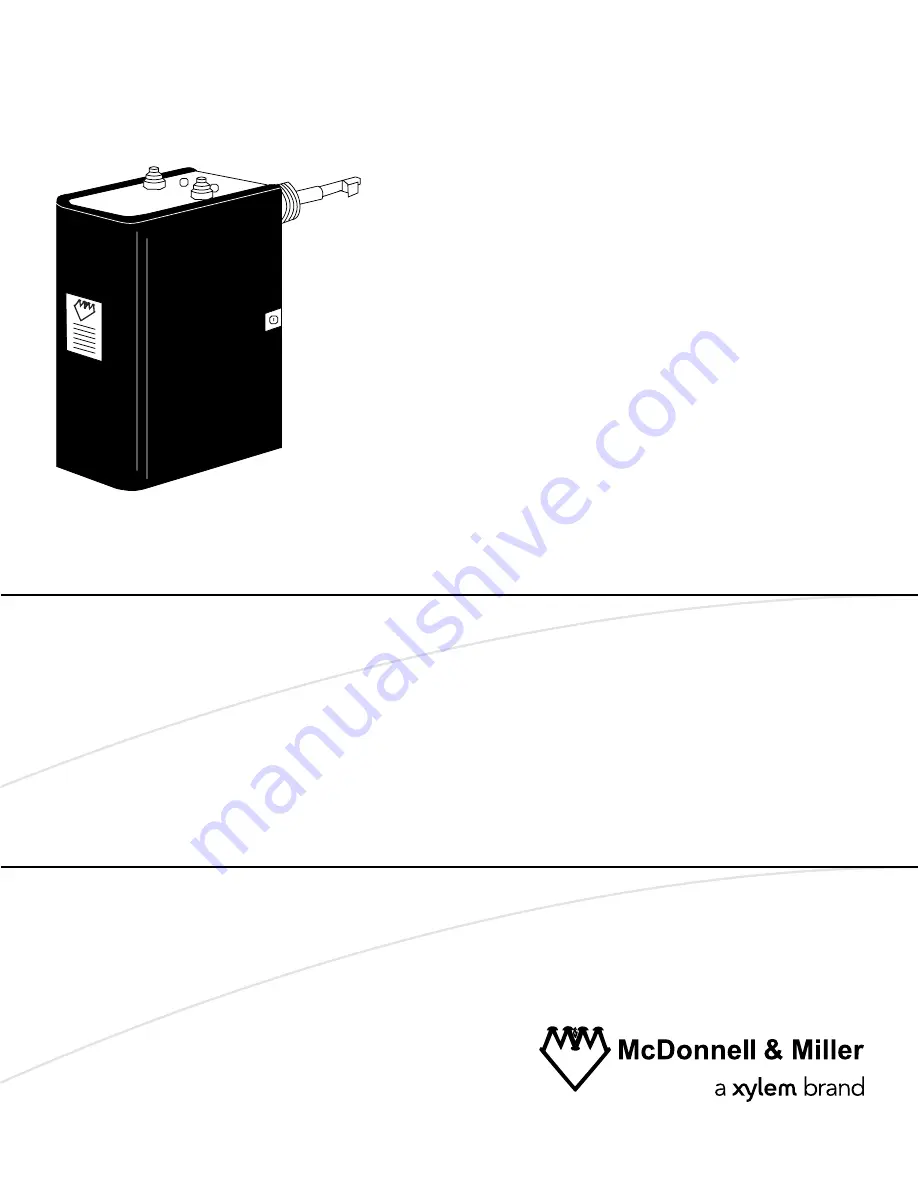
Page 1: ...PSE 800 M Low Water Cut off Installation Operation and Maintenance Manual...

Page 2: ......

Page 3: ...all the control housing 8 Wire the probe to the control housing 8 Control to boiler wiring 9 Electrical conduit connections 9 Wire connections to the terminal block 9 Option A wiring 10 Option B wirin...

Page 4: ...uipment or use of parts not provided by Xylem If there is a question regarding the intended use of the equipment please contact a Xylem representative before proceeding This manual clearly identifies...

Page 5: ...ing specific symbol Electrical Hazard These are examples of other categories that can occur They fall under the ordinary hazard levels and may use complementing symbols Crush hazard Cutting hazard Arc...

Page 6: ...d in this manual The monitoring equipment incorporated in the product is correctly connected and in use All service and repair work is done by Xylem authorized personnel Genuine Xylem parts are used O...

Page 7: ...loss of power as long as there is water on the probe before and after the power loss occurred CSD 1 code compliance For manual reset units when the control is in a low water condition and there is an...

Page 8: ...specifications Ratings Model Control Voltage Motor Switch rating Pilot rating PSE 802 M 24 24 VAC N A 50 VA PSE 802 M U 24 PSE 801 M 120 120 VAC 7 5 FLA 43 2 LRA 125 VA PSE 801 M U 120 Hertz 50 60 Con...

Page 9: ...et low water cut off LWCO Installing the probe above this location could result in nuisance shutdowns or lockouts Install probe in a location above the minimum safe water level as designated by the bo...

Page 10: ...ads 5 Tighten the mounting screws to approximately 2 ft lbs 2 6 N M Steps 2 and 3 Steps 4 and 5 4 6 4 6 Wire the probe to the control housing 1 Slip the ring terminal 7 followed by the lock washer 8 o...

Page 11: ...the new manual reset LWCO turns off when the existing auto reset LWCO detects a low water condition reducing the chance of nuisance lockouts The water feeder continues to operate because there is stil...

Page 12: ...lines indicate new wires Water feeder should be wired to existing Auto Reset LWCO Wiring diagrams for the water feeder can be found in the water feeder installation instruction manual Option B wiring...

Page 13: ...a Model 67 LWCO Voltage of the new manual reset LWCO must be the same voltage as the burner circuit 1 Remove existing wire from terminal 1 of the Model 67 LWCO and connect it to Terminal B of the new...

Page 14: ...2 3 4 N H C W B 1 1 2 3 4 TOP 2 3 4 1 Factory jumper bar 2 To burner 3 Neutral 4 Hot _ _ _ _ Dashed lines indicate existing wires _____ Solid lines indicate new wires Installation 12 PSE 800 M Low Wa...

Page 15: ...he boiler a The burner turns off and the Red light begins to flash when there is no water on the probe b After 60 seconds the red light will stop flashing and will remain on IMPORTANT If water returns...

Page 16: ...r cut off annually Remove and inspect the self cleaning probe every five years Use a non abrasive cloth and rinse with clean water when the probe requires cleaning Do not use sharp instruments to remo...

Page 17: ...specified in the wiring diagrams of the boiler manufacturer or in this instruction manual 3 Check to ensure that PTFE tape has not been used on the threaded connection of the electrode to the boiler 4...

Page 18: ......

Page 19: ......

Page 20: ...150 countries we have strong long standing relationships with customers who know us for our powerful combination of leading product brands and applications expertise backed by a legacy of innovation F...

Reviews: