5400 Series
Cylindrical Knob Lockset
Installation Instructions
Grade 1
• 2 1/8" (54mm) hole saw
• 1" (26mm) boring bit
• 7/64" (2.8mm) drill bit
Tools Required
• Chisel & hammer
• #2 phillips screw driver
• Handle removal tool (supplied)
• 3/8" or I/2" drill
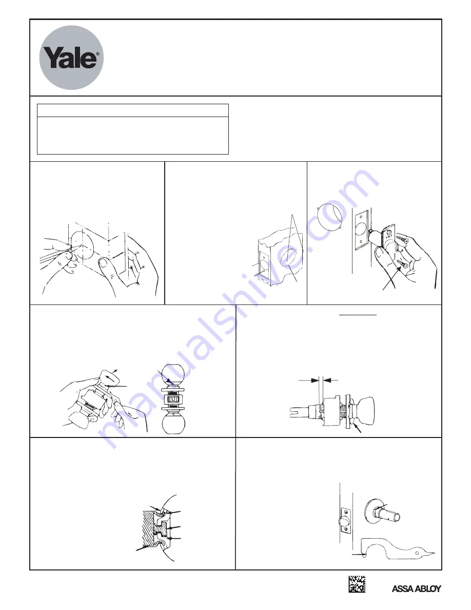
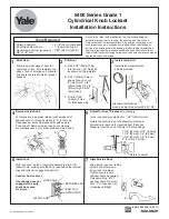
Mark Door
Mark line across edge of door for
centerline of lock. Fold template over
edge of door, centering on horizontal
line. Mark centers of holes at proper
backset.
Drill Door
A. Drill 2-1/8" (54mm) hole
thru the door. Cut Notches
as shown on the template.
B. Drill 1" (25mm) hole in
edge of door. Cut out
for latch front 1-1/8"
(29mm) wide X 2-1/4"
(57mm) high X 5/32"
(4mm) deep.
C. Drill (2) 7/64"
(2.8mm) holes
for latch assembly
2
4
Install Latch Unit
Install latch assembly with
screws provided.
Standard combination
wood and machine screw #8-32 X 3/4”
3
Remove Inside Knob
To remove knob, depress retainer with small end of
spanner wrench, through small hole “A” in trim cap.
Keep spanner wrench perpendicular with spindle.
Pull knob off. Remove inside rose by unscrewing
counterclockwise. For cylinder knob see step 8 and 9.
Install Lock
With lock case in place, insert lock assembly into 2-1/8"
(54mm) hole, making sure that lock case hooks the retainer
legs and retractor engages the bolt tail.
Caution: Do Not Force
If Lockbody does not
engage latch easily,
check door prep
for errors.
LOCK CASE
RETAINER LEG
BOLT TAIL
RETRACTOR
LATCH CASE
Rotate to adjust
1-3/8" (35mm)= 5/16" (8.0mm)
1-1/2" (38mm)= 1/4" (6.5mm)
1-3/4" (44mm)= 1/8" (3.0mm)
2" (51mm)= FLUSH
Adjust for Door Thickness
If necessary
(Lock is packed preadjusted for 1-3/4" (44mm) doors.
Rotate the outside rose nut assembly until proper
dimension is reached for required door thickness.
Measure from the end of the pin to the lock flange.
5
6
“A”
“A”
C
A
Notches
1
4
B
Any retrofit or other field modification to a fire rated opening can
potentially impact the fire rating of the opening, and Yale Locks &
Hardware makes no representations or warranties concerning what
such impact may be in any specific situation. When retrofitting any
portion of an existing fire rated opening, or specifying and installing a
new fire-rated opening, please consult with a code specialist or local
code official (Authority Having Jurisdiction) to ensure compliance with all
applicable codes and ratings.
Attach Inside Rose
Slide inside rose over inside
spindle and sleeve and
screw rose into place.
Tighten securely with
spanner wrench supplied.
Catch small lug “B” of
spanner wrench in small
hole “C” in rose and turn
clockwise until tight.
7
“C”
“B”
An ASSA ABLOY Group brand
80-9150-0003-010 (08-12)


