background image

7100, 7200 Series Exit Device

Delayed Egress

Installation Instructions

Copyright ©2018, 2020 ASSA ABLOY Access and Egress Hardware Group, Inc. All rights reserved. Reproduction in whole or 
in part without the express written permission of ASSA ABLOY Access and Egress Hardware Group, Inc. is prohibited.

For technical support contact Yale

®

 at 800.438.1951 x5033 or support@yalelocks.com

80-9470-0162-000 10/20

This product can expose you to 
lead which is known to the state 
of California to cause cancer and 
birth defects or other reproductive 
harm. For more information go to 
www.P65warnings.ca.gov.

Attention Installer

Any retrofit or other field modification to a fire rated opening
can potentially impact the fire rating of the opening, and
Yale Locks & Hardware makes no representations or
warranties concerning what such impact may be in any
specific situation. When retrofitting any portion of an
existing fire rated opening, or specifying and installing a new
fire-rated opening, please consult with a code specialist or
local code official (Authority Having Jurisdiction) to ensure
compliance with all applicable codes and ratings.

WARNING

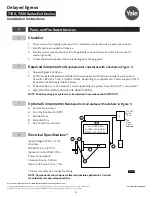
Available on the following devices:

Rim

Mortise

SquareBolt®

Concealed Vertical Rod

*Surface Vertical Rod

*Rod Guards Required (made by other manufacturers

)

Summary of Contents for Delayed Egress 7100 Series

Page 1: ...For more information go to www P65warnings ca gov Attention Installer Any retrofit or other field modification to a fire rated opening can potentially impact the fire rating of the opening and Yale Lo...

Page 2: ...ctrical Specifications 4 2 End Cover and PC BoardAssembly 5 3 DIP Switch Settings 6 4 Installation of End CoverAsssembly to Device 7 5 Device Mounting 8 6 Wiring Layout Input Output Wiring Description...

Page 3: ...Device Installation Instructions 80 9470 0162 000 10 20 TOC Table of Contents 16 Wiring Diagram Single Door with Remote Inputs Monitoring Outputs 21 17 Wiring Diagram O Trim Monitor Entry with Extern...

Page 4: ...tes with numbers in Figure 1 1 Delayed Egress Exit Device 2 24VDC UL Listed Regulated and Filtered Power Supply with Fire Alarm Interface recommend Securitron BPS 24 1 or 24 2 UL294 Listed depending o...

Page 5: ...53 x 2160 cam 1 1 8 mortise cylinder For cylinders over 1 1 8 use Yale 1765 Series cylinder ring Typical Mortise Cylinder 1 Trim device to proper length as required 36 Exit Device 1 maximum can be tri...

Page 6: ...g cylinder key or remote reset signal If door DPS is opened then closed before selected time expires the device will rearm immediately If DPS is not used is bypassed with S2 7 ON the door will rearm i...

Page 7: ...lication see previous page 3 Slide end cover assembly into device making sure not to pinch or crimp wires 4 Connect device lock assembly harness to connector J1 Place wire connectors and excess wire b...

Page 8: ...1 for wire access hole location 2 Feed wires from power transfer through wire access hole in door Figure 4 3 When required mount outside trim to door see trim installation instructions 4 Mount device...

Page 9: ...lay de energizes contact is closed same as Power off state 4 NC EGND Orange Earth Ground connection to PCB mounting plate via ring terminal 5 3 Output Blue Alarm Relay Output J5 jumper Selectable NO N...

Page 10: ...ce per instruction sheet provided 2 Plug exit device connector into raceway connector in door Feed through 1 25mm hole in door Install rail mounting end clamp bracket with two 2 screws supplied Instal...

Page 11: ...ail harness is per facility wiring requirement 2 For an ElectroLynx system go to function or monitor page s with your device 3 Combinations of certain monitors can be used in each device These instruc...

Page 12: ...lelocks com 12 Delayed Egress Installation Instructions 7100 7200 Series Exit Device 80 9470 0162 000 10 20 9 Installing Delayed Egress Exit Device Figure 6 Refer to Figure 6 for delayed egress exit d...

Page 13: ...e REQUIRED 12 wires max If external DPS wiring is REQUIRED Set PCBA Dip Switch S2 7 OFF If LBM Trim Monitor OR Electrified Trim Options are REQUIRED 10 ElectroLynx Wiring Options Overview with QC12 Hi...

Page 14: ...ss written permission of ASSA ABLOY Access and Egress Hardware Group Inc is prohibited For technical support contact Yale at 800 438 1951 x5033 or support yalelocks com 14 Delayed Egress Installation...

Page 15: ...3 or support yalelocks com 15 Delayed Egress 7100 7200 Series Exit Device Installation Instructions 80 9470 0162 000 10 20 11 ElectroLynx Wiring Deed with O Trim Monitor Option and QC12 Hinge QC12 Hin...

Page 16: ...permission of ASSA ABLOY Access and Egress Hardware Group Inc is prohibited For technical support contact Yale at 800 438 1951 x5033 or support yalelocks com 16 Delayed Egress Installation Instruction...

Page 17: ...ed Trim ET Option and QC12 Hinge QC12 Hinge Field Wiring Options Wiring to 8 pin and 4 pin connectors is REQUIRED 12 wires max If external DPS wiring is NOT REQUIRED set PCBA Dip Switch S2 7 ON If ext...

Page 18: ...act Yale at 800 438 1951 x5033 or support yalelocks com 18 Delayed Egress Installation Instructions 7100 7200 Series Exit Device 80 9470 0162 000 10 20 13 ElectroLynx Wiring Deed with S Latchbolt Moni...

Page 19: ...rmission of ASSA ABLOY Access and Egress Hardware Group Inc is prohibited For technical support contact Yale at 800 438 1951 x5033 or support yalelocks com 19 Delayed Egress 7100 7200 Series Exit Devi...

Page 20: ...Details are typical for all opening materials both hands This preparation is an addition to preparation shown on device template See device template to locate centerline Shields for wiring access reco...

Page 21: ...touching device push bar rim will not affect alarm if a door position switch is not being used Refer to DPS wiring if necessary To NC Fire Alarm Contacts 120 VAC Securitron BPS Power Supply Wire Tran...

Page 22: ...Door Position Switch DPS made by other manufacturers Operation Door Position Switch DPS is used to activate alarm when door has been forced open It also prevents device from being armed when door is...

Page 23: ...est sequence is as follows Cover LED is RED for 2 seconds with horn sounding for 500ms Cover LED is then GREEN for 2 seconds followed by AMBER for 1 second with the 4 diagnositc LEDs illuminated Cover...

Page 24: ...tion of momentary egress by cylinder key switch or external remote reset signal if the Door DPS is open beyond 40 seconds it will remain in momentary egress mode indefinitely and shall not enter alarm...

Page 25: ...ened before actual re arming of the device occures A DPS Door Position Switch is required for the BOCA option NOTE BOCA option is not suitable for installations in accordance with NFPA 101 22 BOCA 15...

Page 26: ...ter troubleshooting contact your local hardware distributor or local Yale representative or contact Yale Problem Solution Power is applied but unit will not arm No red LED Check all connections on cir...

Page 27: ...d delay of 15 seconds 0r 30 second optional delay the rail solenoid de energizes and passage is allowed End cover LED is green with alarm at a steady tone which continues until reset by key switch 3 W...

Page 28: ...ion of ASSA ABLOY Access and Egress Hardware Group Inc is prohibited Patent pending and or patent www assaabloydss com patents U S A Yale Locks Hardware Address 225 Episcopal Road Berlin CT 06037 4004...

Reviews: