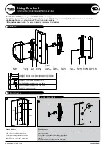
Models:
MC182010B (Locking) and MC182000B (Non-Locking).
Operation:
Key operated cylinder locks and unlocks from outside (locking version only). Snib locks and unlocks from inside.
Application:
For use with aluminium, uPVC and timber sliding doors.
Fitting instructions:
Suitable for new and ideal for replacement installations.
Sliding Door Lock
External Key Locking and Non-Locking
Components
Internal
Handle
Exterior
Handle
Cylinder
(locking
model only)
Cylinder
Retainer
(locking
model only)
Mounting
Screw
(a)
Mounting
Screw
(b)
Strike
Cover
Screw
(e)
Strike
Mounting
Screw
(c)
Strike
Mounting
Screw
(d)
Lock
Body
Strike
Body
Strike
Cover
(a)
2 x M4x49 Mounting screw –
Door stile thickness 40mm-44mm
2 x M4x45 Mounting screw –
Door stile thickness 35mm-40mm
2 x M4x40 Mounting screw –
Door stile thickness 28mm-34mm
(b)
2 x M4x25 Internal handle mounting screws
(c)
2 x 10Gx8 Strike mounting screws – end fixing
(d)
2 x 8Gx25 Strike mounting screws – side fixing
(e)
1 x 8Gx7.5 Strike cover screw
Mark and drill holes
Align template
(cut out from clam card)
on the
inside of the door and drill holes as shown.
If replacing an existing lock utilise any existing
holes if possible.
Note:
Drill centre hole for locking model only.
Fit exterior handle
Exterior handle should be oriented so finger recesses are
next to the door jamb.
Place cylinder in exterior handle with cylinder tailbar aligned
vertically. Assemble cylinder retainer with ‘5 PIN DOWN’ side
showing.
Place exterior handle on outside of door and hold in place.
Fitting Instructions
Locking Model Only
1
2
Cut cylinder tailbar so it protrudes 10mm inside door.
An ASSA ABLOY Group brand
10mm
62.5mm
62.5mm
Ø 10mm
Ø 10mm
Ø 10mm


