background image

1 0 0 6 9 7

SERVICE  MANUAL

AV-S70/NX-SW70

AV-S70/NX-SW70

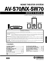
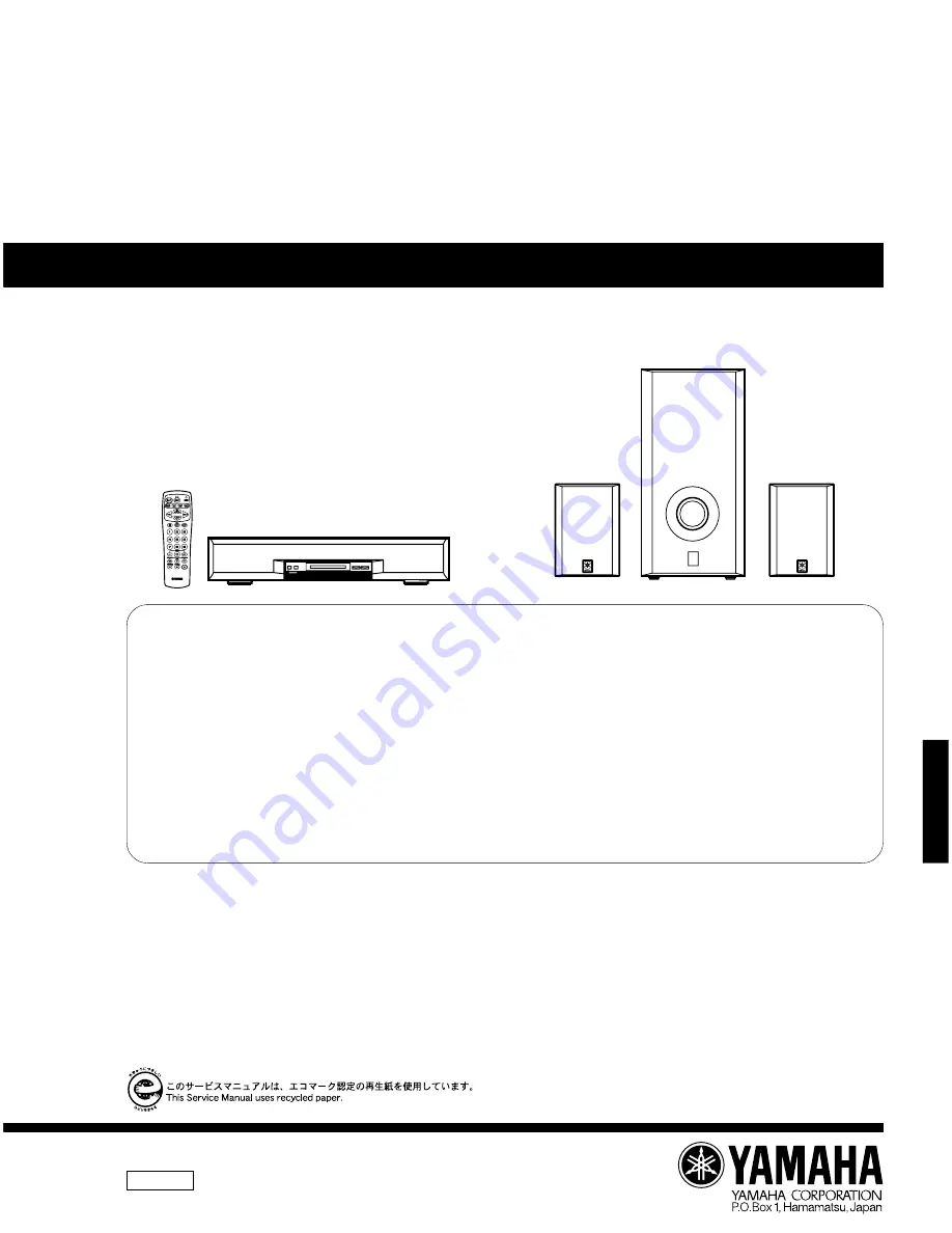
HOME THEATER SYSTEM

NX-SW70 is composed of SW-AVS70 and NX-AVS70s.

CONTENTS

TO SERVICE PERSONNEL ......................................... 1
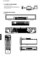
FRONT/REAR PANELS .......................................... 1—2
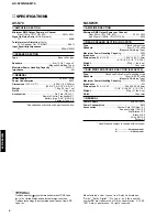
SPECIFICATIONS ......................................................... 3
DISASSEMBLY PROCEDURES .................................. 4
TEST PROGRAM MODE ........................................ 5—6
DSP DIAG MODE ................................................. 7—13
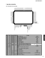
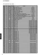
AV-S70 IC DATA ................................................ 14—20
AV-S70 BLOCK DIAGRAM ................................ 21—22

SW-AVS70 BLOCK DIAGRAM .................................. 23
AV-S70 PRINTED CIRCUIT BOARD ................. 24—33
SW-AVS70 PRINTED CIRCUIT BOARD ........... 34—35
AV-S70 SCHEMATIC DIAGRAM ....................... 36—39
SW-AVS70 SCHEMATIC DIAGRAM .......................... 40
PARTS LIST ........................................................ 41—54
REMOTE CONTROL TRANSMITTER ........................ 55

IMPORTANT NOTICE

This manual has been provided for the use of authorized YAMAHA Retailers and their service personnel.
It has been assumed that basic service procedures inherent to the industry, and more specifically YAMAHA Products, are already known and understood by the users,
and have therefore not been restated.

WARNING:

Failure to follow appropriate service and safety procedures when servicing this product  may result in personal injury, destruction of expensive
components, and failure of the  product to perform as specified. For these reasons, we advise all YAMAHA product owners that any service
required should be performed by an authorized YAMAHA Retailer or the appointed service representative.

IMPORTANT:

The presentation or sale of this manual to any individual or firm does not constitute authorization,  certification  or  recognition  of  any  applicable
technical  capabilities,  or establish a principle-agent relationship of any form.

The data provided is believed to be accurate and applicable to the unit(s) indicated on the cover.  The research, engineering, and service departments of YAMAHA are
continually striving  to improve YAMAHA products. Modifications are, therefore, inevitable and specifications are subject to change without notice or obligation to
retrofit. Should any discrepancy appear to exist, please contact the distributor's Service Division.

WARNING:

Static discharges can destroy expensive components. Discharge any static electricity your body may have accumulated by grounding yourself to the
ground buss in the unit (heavy gauge black wires connect to this buss).

IMPORTANT:

Turn the unit OFF during disassembly and part replacement. Recheck all work before you apply power to the unit.

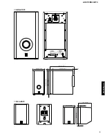
FRONT SPEAKER (AV-S70)

SUBWOOFER

(SW-AVS70)

REAR SPEAKER

(NX-AVS70)

REAR SPEAKER

(NX-AVS70)

Summary of Contents for AV-S70

Page 1: ...these reasons we advise all YAMAHA product owners that any service required should be performed by an authorized YAMAHA Retailer or the appointed service representative IMPORTANT The presentation or sale of this manual to any individual or firm does not constitute authorization certification or recognition of any applicable technical capabilities or establish a principle agent relationship of any ...

Page 2: ...0 3 8 AV S70 1 TO SERVICE PERSONNEL Critical Components Information Components having special characteristics are marked Z and must be replaced with parts having specifications equal to those originally installed AC LEAKAGE TESTER OR EQUIVALENT EQUIPMENT UNDER TEST INSULATING TABLE WALL OUTLET FRONT REAR PANELS ...

Page 3: ...AV S70 NX SW70 AV S70 NX SW70 200 6 7 7 8 40 1 3 4 335 13 3 16 24 15 16 399 15 11 16 390 1 15 3 8 5 5 3 16 395 6 15 9 16 100 3 15 16 20 13 16 111 5 4 3 8 140 5 1 2 1 4 1 16 SW AVS70 NX AVS70 2 ...

Page 4: ...30V 50Hz Power Consumption 80W Accessories System Cord DIN plug X 1 Speaker Cable 15m X 2 Wall Bracket X 2 Bracket X 2 Wing Bolt X 2 Screw X 2 Specifications subject to change without notice AV S70 AMPLIFIER SECTION Minimum RMS Output Power per Channel Front 1kHz 10 THD 6Ω 30W 30W Signal to Noise Ratio IHF A Network TV 85dB Total Harmonic Distortion 1kHz TV to Speaker Out 12 5W 6Ω 0 08 Input Sensi...

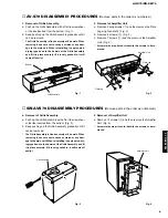
Page 5: ...bly is fixed securely at 6 dowels When removing it use care not to cause a scratch or any dam age to the main unit When reinstalling it apply quick dry ing type bond to the dowels of the Grille Assembly and fit it in place securely If it is only pushed in it will come off easily SW AVS70 DISASSEMBLY PROCEDURES Remove parts in the order as numbered Fig 1 Grill Assembly q q Amplifier Unit Fig 2 q e ...

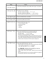
Page 6: ...r b Select the Test Program 01 DEST Ex and press the INPUT key for execution The normal mode will be restored 4 Details of the Test Program function Display 01 DEST B G1 Function Destination display test program end Destination display J Ja J Japanese J En J English B G1 B G models 02 FL CLEAR FL display segments all light up BACKUP RAM CLEAR 1st time FL display segments all light up and standby L...

Page 7: ...lay 09 Cors 288b When there is no data NON appears on the display The ROM collection EEPROM is utilized to cope with the data area for backup and microprocessor bugs partially The backup memory for the sound field or the like will be retained semi permanently even when the plug is disconnected No data is written in the parts mounted on the product as single units 10 COR Clear ROM collection EEPROM...

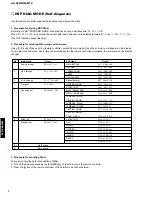
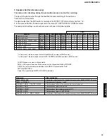
Page 8: ...hrough AC 3 Through 4 Pro logic Pro Logic 5 Speakers set Speakers Set 6 Effect off Effect Off 7 Manual test Manual Test 8 No function 9 DIAG cancel Sub menu Display MAIN BYPASS A T M Bypass DSP 0dB A T DSP 0dB YSS908 SRAM DspT 908SRAM YS908 DspT YSS908 DSP FULL BIT DspT FullBit Status Binary AC3 Analo2 0 CENTER LARGE ProL CenterL EFFECT OFF ProL Eff Off MAIN SMALL 0dB Sp MainS 0dB MAIN LARGE 0dB S...

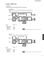
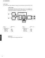
Page 9: ...X IN 20dBV Both ch VOLUME MAX CN102 Page 30 C 4 MAIN L 1kHz 20dBV MAIN R 1kHz 20dBV LFE 30Hz 34dBV REAR L 1kHz 26dBV REAR R 1kHz 26dBV DIR2 CODEC DA CS4227 YM3436 CODEC AD AC3Dav YSS908 CS4227 DECODER 256K SRAM DSP ANALOG IN L R L R REAR L REAR R CENTER LFE L R L R DIGITAL IN MAIN R MAIN L DIR2 CODEC DA CS4227 YM3436 CODEC AD AC3Dav YSS908 CS4227 DECODER 256K SRAM DSP ANALOG IN L R L R MAIN R REAR...

Page 10: ...L R 2 DIR2 CODEC DA CS4227 YM3436 CODEC AD AC3Dav YSS908 CS4227 DECODER 256K SRAM DSP ANALOG IN REAR L REAR R DIGITAL IN MAIN R MAIN L L R L R 2 L R 2 CENTER LFE L R DIR2 CODEC DA CS4227 YM3436 CODEC AD AC3Dav YSS908 CS4227 DECODER 256K SRAM DSP ANALOG IN L R REAR L REAR R CENTER LFE L R L R L R DIGITAL IN MAIN R MAIN L AUX IN 20dBV Both ch VOLUME MAX CN102 Page 30 C 4 MAIN L 1kHz 20dBV MAIN R 1kH...

Page 11: ...ion the source DAT CD ROM etc without digital data bit of IEC958 cannot be reproduced even when it is AC 3 encoded On the other hand as this menu does not execute such digital data bit identification these sources can be AC 3 reproduced To measure characteristics during AC 3 reproduction use the AC 3 decoded sine wave However note that with the sources that have not been AC 3 encoded a decode erro...

Page 12: ...e signals are AC 3 reproduced EFFECT OFF The L R signal is output through MAIN BYPASS DIR2 CODEC DA CS4227 YM3436 CODEC AD AC3Dav YSS908 CS4227 DECODER DOLBY DIGITAL or PRO LOGIC 256K SRAM DSP ANALOG IN C S C S REAR L REAR R CENTER DIGITAL IN L R L R MAIN R MAIN L AUX IN 20dBV Both ch VOLUME MAX CN102 Page 30 C 4 MAIN L 1kHz 20dBV MAIN R 1kHz 20dBV LFE 30Hz 28dBV REAR L 1kHz 45dBV REAR R 1kHz 45dB...

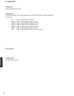
Page 13: ...e channel specified by LFE BASS NONE The center contents are distributed to the MAIN L R channels after 3dB SWFR SUBWOOFER Output The signal before MASTER VOLUME is indicated In Sub menu 1 the lower range content of the MAIN L R is output at SWFR as well In Sub menu 7 the lower range content of LFE CENTER and REAR is output at SWFR as well Sub menu Main application MAIN SMALL 0dB Confirmation of h...

Page 14: ...AIN L Noise is output through the MAIN L channel CENTER Noise is output through the CENTER channel MAIN R Noise is output through the MAIN R channel REAR R Noise is output through the REAR R channel REAR L Noise is output through the REAR L channel LFE Noise is output through the LFE sub woofer channel 6 Effect Off All effect functions are turned off 8 No function 9 DIAG cancel The DSP DIAG is can...

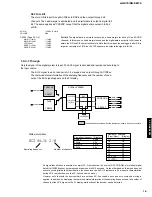
Page 15: ...TB2 P91 SBUSY2 P90 SRDY2 CNVSS P87 XCIN P86 XCOUT RESET XOUT VSS XIN VCC P85 INT5 P84 INT4 P83 INT3 P82 INT2 P81 INT1 P80 INT0 P77 TA4IN TA2OUT CTS1 RTS1 CLKS1 P76 TA3IN TA1OUT CLK1 P75 TA2IN TA0OUT RXD1 P74 TA1IN TA4OUT TXD1 P73 TA0IN TA3OUT P72 TB2IN P71 TB1IN P70 TB0IN No PORT Name IN OUT Function 1 P97 CMOS OUT BASS BOOST OUT 0 ON 2 P96 CMOS OUT Center unit RL RR SW MUTE OUT 0 MUTE ON 3 P95 CM...

Page 16: ... pull down required 47 P27 FLD39 OUT DIGIT 5 5G VEE external pull down required 48 P26 FLD38 OUT DIGIT 4 4G VEE external pull down required 49 P25 FLD37 OUT DIGIT 3 3G VEE external pull down required 50 P24 FLD36 OUT DIGIT 2 2G VEE external pull down required 51 P23 FLD35 OUT DIGIT 1 1G VEE external pull down required 52 P22 FLD34 OUT SEGMENT 1 P1 VEE external pull down required 53 P21 FLD33 OUT S...

Page 17: ...0 5 0V SW provided 2 5V SW not provided 0 2 0V SW protection ON 91 P106 AN6 A D IN AUTO POWER ON OFF identify IN music signal 0 VREF 92 P105 AN5 A D IN Center unit power supply voltage detect IN protection 0 VREF 93 P104 CMOS OUT Night mode switching OUT 1 ON 94 P103 CMOS OUT Center unit power supply OUT 1 ON 95 P102 AN2 A D IN Destination select input Pull up with 10kΩ VREF 96 P101 AN1 A D IN KEY...

Page 18: ... Fs x 1 Synchronous output signal for DAC Fs x 1 Synchronous output signal for DSP Fs x 64Bit clock output Fs x 1Word clock output Fs x 128Bit clock output Fs x 256Bit clock output Clock synchronization control input Crystal oscillator connection or external clock input Crystal oscillator connection VCO oscillating clock connection PLL lock flag Logic section power GND PLL time constant switching ...

Page 19: ... SDIB0 SDIB1 SDIB2 XI XO PVSS AVDD TEST TEST TEST OVFB TEST TEST TEST CPO AVSS 30 29 28 27 26 25 24 23 22 21 VDD SDOA2 SDOA1 SDOA0 RAMA14 RAMA13 RAMA12 RAMA11 RAMA10 VSS TOP VIEW SDBCK0 CONTROL SIGNALS SDI SERIAL DATA INPUT SDO SERIAL DATA OUTPUT CONTROL SIGNALS CONTROL REGISTERS INPUT BUFFER PLL OPERATING CLOCK 25MHz STREAM0 7 L R Ls Rs C LFE DELAY RAM ERAMUSE EXTERNAL RAM INTERFACE DATA RAM MAIN...

Page 20: ...inal from Main DSP L R output at both AC 3 DTS and Pro Logic 25 RAMA14 O External SRAM address terminal 14 26 RAMA13 O External SRAM address terminal 13 27 RAMA12 O External SRAM address terminal 12 28 RAMA11 O External SRAM address terminal 11 29 RAMA10 O External SRAM address terminal 10 30 VSS Ground terminal for internal circuit 31 PVDD 5V power terminal 32 OPORT0 O General purpose output term...

Page 21: ... RAMD3 I O External SRAM data terminal STREAM 3 output when external SRAM is not used 76 RAMD4 I O External SRAM data terminal STREAM 4 output when external SRAM is not used 77 RAMD5 I O External SRAM data terminal STREAM 5 output when external SRAM is not used 78 RAMD6 I O External SRAM data terminal STREAM 6 output when external SRAM is not used 79 RAMD7 I O External SRAM data terminal STREAM 7 ...

Page 22: ...DIGITAL VOLUME IC106 TC9482N CLK STB 5 6 7 ML 26 MR 20 LFE 6 RL 23 RR M5220FP L IC104 R IC105 SIGNAL SENSOR 3 2 1 M5220FP L IC104 R IC105 CN102 GO TO CN601 WOOFER P C B POWER AMP M SENSOR IC107 L L R R L R L R L R INPUT 1 AUX INPUT 2 TV INPUT 3 VIDEO THROU 2 1 DIGITAL LOCKN Q101 Q102 Q103 Q104 7 B A 3 DATA L 10 mV M 5 mV H 3mV Page 37 Page 36 3 1 5 7 5 7 IC603 UPC4570G2 UPC4570G2 Q606 Q607 IC601 U...

Page 23: ...INPUT AVSS AVCC VP CE FCE E2CE FRX STB 28 31 CE 10 ISELA ISELB MUSIC CPAT PREOUT ISEL A 11 ISEL B TRUBASS 91 M SENSOR 37 PRE OUT 20 64 98 96 38 89 100 63 16 97 14 65 58 59 1 2 AMP PRT DATA XL701 CONTROL 6CH SELECTOR 6CH VOLUME CONTROL INPUT SELECTOR SIGNAL DETECT FOR AUTO POWER PRE OUT PRESENT ABSENT DC SIGNAL DETECT IC701 M30218FCFP 88 66 54 42 40 6 62 52 51 39 V701 FL DISPLAY Q703 Q704 Q701 Q708...

Page 24: ...T Q115 R167 R168 IC104 IC105 UPC4570 R174 RY102 SUB WOOFER RELAY RY101 REAR SPEAKER RELAY SUB WOOFER Q118 REAR SPEAKER LCH REAR SPEAKER RCH Q106 Q107 DC SIGNAL DETECT Q113 Q114 PROTECTION CIRCUIT Q103 Q105 OVER CURRENT DETECT 0 22Ω 3W Q104 Q105 OVER CURRENT DETECT IC106 1 3 IC108 D108 1 3 IC107 1 2 Q117 Q116 D109 F101 RY103 RELAY CONTROL SW POWER SW PRT T101 R195 CURRENT DETECTOR Page 40 SW AVS70 ...

Page 25: ...RXDO CE RESET VCC CLKO TXDO DIGITAL 1 DIGITAL 2 DSP FL A P C B Component side DSP FL A P C B Foil side Point q Pin 13 of IC3 V 2V div H 0 1 µsec div DC 1 1 probe 0V 24 25 Ref No Location D1 F2 D2 F2 D3 B4 D4 B4 D5 C3 D6 C3 D7 C3 D8 C3 D9 C3 D10 C3 D11 C3 D12 C3 Ref No Location IC1 C2 IC2 C2 IC3 C3 IC4 C4 IC6 C3 IC7 C4 IC8 B4 IC9 B3 IC10 B3 IC11 B3 IC12 B3 IC15 C4 IC801 C2 IC802 C2 Semiconductor Lo...

Page 26: ...5V SW RY P ON B BST NIGHT CLK CE M SENSOR ISEL A DSP FL B P C B Foil side Point w Pin 13 of IC701 V 2V div H 0 1 µsec div DC 1 1 probe 0V Point e 10V Emitter of Q706 RESET Collector of Q705 V 2V div 10V V 2V div RESET DC 1 1 probe H 1 sec div 0V 0V AC CORD ON AC CORD OFF 10V RESET 26 27 Ref No Location D701 D2 D702 D5 D703 C2 D704 C2 D705 C2 D706 C2 D707 B3 D708 C3 Ref No Location IC801 D2 IC802 C...

Page 27: ...TPUT SYSTEM CONECTOR 15V 15 V MUTE 15V 15V SP RY SW PRT PRE OUT TruBass AMP PRT B BST NIGHT L RL R G RR SW G RE RE TO AMP B FROM AMP A AMP C P C B Foil side 28 29 Ref No Location D501 B3 Ref No Location IC501 B2 IC502 B3 IC503 A2 Semiconductor Location Ref No Location Q501 A4 Q502 B4 Q503 B4 Q504 B4 Q505 B3 Q506 B2 Ref No Location D602 E4 D603 E3 Ref No Location IC601 G3 IC602 G3 IC603 G4 IC604 G4...

Page 28: ... 25VEL SW RY P ON B BST NIGHT CLK CE M SENSOR ISEL A MUTE 15 15 SP RY SW PRT PRE OUT TruBass AMP PRT B BST NIGHT AMP E P C B Component side FROM AMP D POWER 30 31 Ref No Location D101 E3 D102 E3 D103 D3 D104 D3 D105 D3 D106 D3 D110 E4 D111 E4 D301 B4 D302 A4 D303 C5 D304 C5 D305 C5 D307 A4 D308 B3 D309 B3 D310 C4 D311 B4 D313 C4 D314 A4 Ref No Location IC103 D4 IC106 D4 IC121 C3 IC122 C4 IC123 C3 ...

Page 29: ...SW70 AV S70 PRINTED CIRCUIT BOARD AMP A P C B Foil side AMP D P C B Component side RE RE RE RE YE TO AMP B TO AMP E TO AMP A FROM POWER CORD 32 33 Ref No Location IC101 A3 IC102 A3 IC104 B3 IC105 A3 IC107 A4 IC120 C4 Semiconductor Location ...

Page 30: ...M POWER CORD AMP C P C B Component side RE 34 35 Ref No Location D101 C3 D102 C4 D103 C2 D104 C3 D105 C3 D106 C3 D107 B4 D108 B4 D109 A3 D110 C3 D111 C3 D112 F4 D113 F2 Ref No Location IC101 B2 IC102 B3 IC103 B3 IC104 C3 IC105 C3 IC106 B3 IC107 B3 IC108 C4 IC109 B1 Semiconductor Location Ref No Location Q101 C3 Q102 C2 Q103 A1 Q104 A2 Q105 A2 Q106 C2 Q107 C2 Q108 C3 Q109 C3 Q110 C3 Q111 C3 Q112 C4...

Page 31: ...ODER WITH INHIBIT SW SW SW SW SW SW SW SW 13 X 3 Y INHIBIT 0 0 0 0 1 B 0 0 1 1 X A 0 1 0 1 X 0x 0y 1x 1y 2x 2y 3x 3y NONE IC102 107 µPC4570G2 IC104 105 M5220FP Dual OP Amp OUT1 IN1 VCC VCC OUT2 1 2 3 4 5 IN1 IN2 IN2 6 7 8 All voltage are measured with a 10MΩ V DC electric volt meter Components having special characteristics are marked Z and must be replaced with parts having specifications equal t...

Page 32: ...RAM IC6 CS4227 KP AD Converter DA Converter All voltage are measured with a 10MΩ V DC electric volt meter Components having special characteristics are marked Z and must be replaced with parts having specifications equal to those originally installed Schematic diagram is subject to change without notice A14 A12 A7 A6 A5 A4 A3 A2 A1 A0 I O1 I O2 I O3 GND 1 2 3 4 5 6 7 8 9 10 11 12 13 14 VCC WE A13 ...

Page 33: ...1 1 probe H 1 sec div 0V 0V AC CORD ON AC CORD OFF 10V RESET AV S70 SCHEMATIC DIAGRAM 3 4 All voltage are measured with a 10MΩ V DC electric volt meter Components having special characteristics are marked Z and must be replaced with parts having specifications equal to those originally installed Schematic diagram is subject to change without notice V701 13 BT 169GNK V4879700 Note 1 F1 F2 Filament ...

Page 34: ...W B SW C SIG A SIG B SIG D SIG C IC503 TRUBASS Bass Enhancement Processor IC501 502 LM1875T Power Amp IN IN VEE OUTPUT VCC 1 2 3 4 5 All voltage are measured with a 10MΩ V DC electric volt meter Components having special characteristics are marked Z and must be replaced with parts having specifications equal to those originally installed Schematic diagram is subject to change without notice 24 23 ...

Page 35: ...408 040E 3 Channel AF Power Amp All voltage are measured with a 10MΩ V DC electric volt meter Components having special characteristics are marked Z and must be replaced with parts having specifications equal to those originally installed Schematic diagram is subject to change without notice 20 19 18 17 16 15 14 13 12 11 10 9 8 7 6 5 4 3 2 1 THERMAL SENSOR SUB CH 1 CH 3 CH 2 SUB GND N C CH 2 VCC C...

Page 36: ...IGHT EMITTING MODULE LED DSPLY LED DISPLAY LED INFRD LED INFRARED MODUL RF MODULATOR RF PHOT CPL PHOTO COUPLER PHOT INTR PHOTO INTERRUPTER PHOT RFLCT PHOTO REFLECTOR PIN TEST PIN TEST POINT PLST RIVET PLASTIC RIVET R ARRAY RESISTOR ARRAY R CAR CARBON RESISTOR R CAR CHP CHIP RESISTOR R CAR FP FLAME PROOF CARBON RESISTOR R FUS FUSABLE RESISTOR R MTL CHP CHIP METAL FILM RESISTOR R MTL FLM METAL FILM ...

Page 37: ... 066286 C301 AAX11280 C POL 0 047uF 50V 065118 C302 AAX11280 C POL 0 047uF 50V 065118 C303 AAX10370 C EL 4700uF 35V 066451 C304 AAX10370 C EL 4700uF 35V 066451 C305 AAX11180 C POL 0 1uF 50V 065007 C306 AAX10300 C EL 33uF 16V 066389 C308 AAX10220 C EL 1000uF 6 3V 066315 C309 AAX10410 C EL 6800uF 16V 066466 C311 AAX10150 C EL 10uF 16V 066282 C312 AAX11280 C POL 0 047uF 50V 065118 C313 AAX11280 C POL...

Page 38: ...103 AAX10520 CN 53291 1191 055458 CN105 VM389000 CN 52045 2345 081830 CN110 AAX10560 CN B 3P VH 081665 CN111 VC014600 CN B02B EH 081439 CN112 VL844700 CN XH B3B 081461 CN405 AAX10550 CN S2P3 VH 081663 CN501 VC015000 CN EH 6P 081522 CN502 LB932020 CN BS PIN 2P 081661 CN503 AAX10570 CN B 5P VH 081672 CN504 AAX10590 CN B2P3 VH 081855 CN505 VC014800 CN EH 4P 081493 CN601 AAX10490 CN 52419 0790 055455 ...

Page 39: ...0 R MTL FLM 27Ω 1W 067950 Z R337 VK186900 R FUS 18Ω 1 4W 057098 Z R338 VK186900 R FUS 18Ω 1 4W 057098 Z R339 VE009700 R FUS 100Ω 1 4W 057099 Z R340 VE009700 R FUS 100Ω 1 4W 057099 R341 AAX11950 R CAR FP 1Ω 1 4W 084665 R401 AAX11900 R CAR FP 2 2Ω 1 4W 055504 R402 AAX11900 R CAR FP 2 2Ω 1 4W 055504 R513 AAX11930 R CAR FP 820Ω 1 4W 055507 R517 AAX11920 R CAR FP 6 8Ω 1 4W 055506 R522 AAX11920 R CAR FP...

Page 40: ...6 AAX11190 C POL 1200pF 50V 065014 C77 AAX11230 C POL 0 27uF 50V 065082 C78 AAX10160 C EL 10uF 25V 066286 C79 AAX10160 C EL 10uF 25V 066286 C80 AAX11240 C POL 3300pF 50V 065087 C81 AAX11240 C POL 3300pF 50V 065087 C81 AAX11240 C POL 3300pF 50V 065087 C82 AAX10160 C EL 10uF 25V 066286 C83 AAX11120 C POL 10pF 50V 055439 C84 AAX11120 C POL 10pF 50V 055439 C85 AAX11120 C POL 10pF 50V 055439 C86 AAX111...

Page 41: ... M5220FP 055465 IC9 XV039A00 IC M5220FP 055465 IC10 XV039A00 IC M5220FP 055465 IC11 XV039A00 IC M5220FP 055465 IC12 XV039A00 IC M5220FP 055465 IC15 XU965A00 IC uPC29M33T E1 055304 IC701 XY514A00 IC M30217MA A201FP 058130 IC702 AAX10090 IC S 29390AFJA TB 055306 IC801 XS993A00 IC TC74HCU04AF T 070867 IC802 XR042A00 IC TC74HC153AF 070781 JK801 V2508700 CN PHOT SN GP1F37R 055510 L1 GE300610 FER CORE F...

Page 42: ...R CAR CHP 330Ω 1 8W 067756 AAX11630 R CAR CHP 33KΩ 1 8W 067760 AAX11640 R CAR CHP 3 6KΩ 1 8W 067764 AAX11650 R CAR CHP 390Ω 1 8W 067767 AAX11660 R CAR CHP 3 9KΩ 1 8W 067769 AAX11670 R CAR CHP 39KΩ 1 8W 067771 AAX11680 R CAR CHP 47Ω 1 8W 067776 AAX11690 R CAR CHP 470Ω 1 8W 067777 AAX11700 R CAR CHP 470KΩ 1 8W 067782 AAX11710 R CAR CHP 4 7Ω 1 8W 067785 AAX11730 R CAR CHP 5 1KΩ 1 8W 067788 AAX11740 R...

Page 43: ...6402 C148 AAX12450 C POL 3900pF 50V 065099 C149 AAX11170 C POL 0 47uF 50V 064936 C151 AAX11270 C POL 4700pF 50V 065111 C152 AAX12260 C EL 33uF 25V 066391 C153 AAX12410 C POL 0 18uF 50V 064917 C154 AAX11180 C POL 0 1uF 50V 065007 C155 AAX10150 C EL 10uF 16V 066282 C156 AAX10150 C EL 10uF 16V 066282 C157 AAX10150 C EL 10uF 16V 066282 C158 AAX12270 C EL 330uF 16V 066402 C159 AAX12270 C EL 330uF 16V 0...

Page 44: ...1 AAX12360 R MTL PLAT 0 22Ω 3W 055474 R141 AAX11870 R CAR FP 10Ω 1 4W 044452 R142 AAX11870 R CAR FP 10Ω 1 4W 044452 R147 AAX09880 R CAR FP 22Ω 1 4W 054214 R148 AAX09880 R CAR FP 22Ω 1 4W 054214 R166 AAX11860 R CAR FP 100Ω 1 4W 044153 R167 AAX11880 R CAR FP 1KΩ 1 4W 044454 R168 AAX11880 R CAR FP 1KΩ 1 4W 044454 R177 AAX11900 R CAR FP 2 2Ω 1 4W 055504 R178 AAX11930 R CAR FP 820Ω 1 4W 055507 R179 AAX...

Page 45: ... 5 1 3 1 8 1 8 1 4 1 11 1 11 1 1 2 6 2 22 2 13 2 8 2 3 2 19 2 19 2 19 2 16 2 12 2 7 3 E 4 B 3 D 3 B 3 A 3 C 4 A 1 1 2 4 1 2 1 4 1 6 1 10 1 11 1 11 1 12 1 9 1 6 1 10 2 19 2 19 2 19 2 19 2 19 1 12 1 9 1 7 2 21 2 28 2 17 2 24 2 30 2 11 2 10 1 5 1 8 1 8 2 2 7 2 2 5 2 2 5 2 2 7 1 13 2 29 2 27 2 18 2 24 2 26 2 26 2 24 2 24 2 24 2 24 2 9 2 25 2 2 2 2 2 3 2 25 2 23 2 23 2 23 2 23 2 23 ...

Page 46: ...WER SW 054918 2 4 AAX11290 MOLD FRONT 054919 2 5 AAX10920 MOLD HEATSINK COVER 054920 2 6 AAX14920 BUTTON POWER SW 059547 2 7 AAX10050 DECO FL FILTER 054922 2 8 AAX10780 DECO DISPLAY 054923 2 9 AAX10650 SPACER KGLS 22S 055170 2 10 AAX10630 CHASSIS 057186 2 11 AAX10620 SHIELD COVER 056884 2 12 AAX10120 INSULATOR POWER SW 056885 2 13 AAX10130 CUSHION 8x25x6 056892 Z 2 14 VZ163900 POWER CORD B 055284 ...

Page 47: ...ion Remarks Markets New Parts AV S70 NX SW70 AV S70 NX SW70 52 ACCESSORIES 200 V5633900 REMOTE CONTROL 059946 200 1 AAX15160 LID 331540 AAX11350 FASTENER TAPE 2pcs 055593 AAX10940 PIN CORD 2p 3mx1 055701 BATTERY SUM4 AAA R03 ...

Page 48: ... 10 2 15 2 15 2 10 2 10 2 11 2 7 1 2 12 1 7 1 7 1 7 1 7 1 7 2 14 2 5 1 6 1 6 1 8 1 4 207 206 204 205 202 4 203 1 4 1 5 1 1 1 2 2 4 2 7 5 2 7 4 2 7 7 2 7 6 2 9 2 9 2 18 2 17 2 8 2 7 2 2 7 3 2 16 2 6 2 17 2 18 3 B 3 A 3 C 1 7 1 7 2 1 2 3 SW AVS70 EXPLODED VIEW ...

Page 49: ... 7 5 AAX11970 IC STK408 040E 049670 IC109 2 7 6 AAX12380 PAN HEAD B TITE SCREW 3x20 BL 055430 2 7 7 AAX12090 BIND HEAD B TITE SCREW 3x12 BL 075642 2 8 AAX12160 BRACKET CLIP L80 A 078004 2 9 AAX12080 BIND HEAD B TITE SCREW 3x6 ZC 075633 2 10 AAX12090 BIND HEAD B TITE SCREW 3x12 BL 075642 2 11 AAX12100 BIND HEAD B TITE SCREW 4x10 BL 075659 Z 2 12 VZ163900 POWER CORD B 055284 Z 2 12 VZ164000 POWER CO...

Page 50: ... 14 13 15 39 16 17 38 X2 IC X1 VSS VSS VDD VDD 24 P31 INTP1 P32 INTP2 CPT2 23 26 P22 RXD S10 P03 33 29 P07 NC 30 P06 NC 31 P05 NC 32 P04 NC 34 P02 NC 35 P01 NC 38 P00 NC 12 NC NC 37 NC NC R4 1MΩ R3 220kΩ VBAT C5 0 01µF 25 P30 INTP0 R7 470kΩ VDD C6 0 1µF K65 VDD X1 4 0MHz C1 470µF C2 0 1µF C3 0 1µF C4 OPTION VDD VBAT BAT 1 5V x 2 Q1 2N3904 IC1 10 11 12 16 18 19 20 21 22 23 26 27 28 29 30 31 34 35 3...

Page 51: ... HF85 4150 HF45 4220 HF85 4270 HF45 4330 HF85 4390 HF45 4470 HF45 4560 HF45 4680 HF45 4750 HF45 4820 HF45 4910 HF45 5100 HF85 5110 HF45 5120 HF45 5150 HF45 5180 HF45 5200 HF45 5220 HF45 5270 HF45 5330 HF45 5390 HF45 5430 HF45 5470 HF45 5510 HF45 5560 HF45 5680 HF45 5820 HF45 5910 HF45 6100 HF45 6120 HF45 6150 HF45 6180 HF85 6200 HF45 6220 HF85 6240 HF45 6270 HF45 6300 HF45 6330 HF85 6360 HF45 6390...

Reviews: