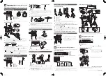
This manual describes the standard assembly of the DTX550K.
After assembling the parts and connecting the cords as shown in Figure 1, the
unit is ready to be turned on.
* To assemble the unit, make sure you have the following four packages:
- RS85A (Electronic Drum Rack)
- DTP502 (Pad Set)
- DTX500 (Trigger Module)
- XP100SD (3-zone Drum Pad)
NOTICE Before assembling the unit, lay a drum mat (sold separately).
Before assembling the unit, lay a drum mat on the floor. Alternately, to prevent
damaging your floor, lay the cardboard of the included packages, etc. on the
floor before assembling the two parts shown in the circles in Figure 1.
Figure 1: Unit Standard Assembly
q
DTX500 (Drum Trigger Module)
w
RHH135 (Real Hi-Hat Pad)
e
XP100SD (3-zone Drum Pad)
r
HS650A (Hi-Hat Stand)
t
AC Adaptor
y
PCY135 (3-zone Cymbal Pad)
u
PCY155 (3-zone Cymbal Pad)
i
TP65 (Drum Pad)
o
KP65 (Kick Pad)
!0
RS85A (Electronic Drum Rack)
Checking the contents of RS85A
Open the RS85A (Electronic Drum Rack) package and confirm the contents.
Figure 2: Electronic Drum Rack RS85A
RS85A (1)
Rubber Foot (2)
Cable Band (6)
*
1
Assembly Manual (1)
*
2
-RS85A
*1 Use cable bands to bind cables to pipes in “ Connecting to a power source”. (Spare bands are included.)
*2 Not this manual.
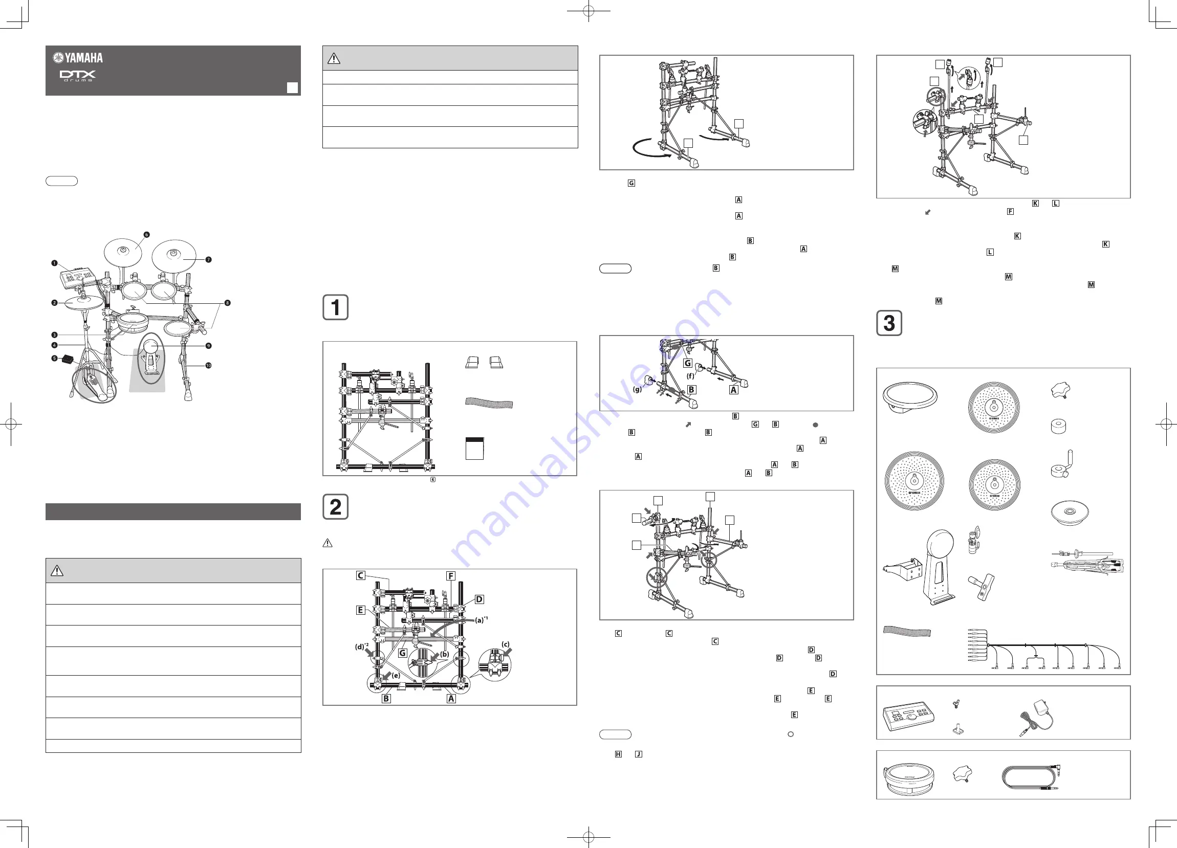
Assembling the Electronic Drum Rack
1
Take out the electronic drum rack from the package and remove all the cushioning. Remove
the bubble wrap on the pipes while assembling the electronic drum rack.
CAUTION
The pipe ends may injure your fingers.
Figure 3: Rack Assembly-1
*1 YAMAHA logo label on the curved pipe is facing the opposite side.
*2 The knob is on the opposite side of the pipe.
Figure 4: Rack Assembly-2
A
B
2
See Figure 3. Set up the electronic drum rack, with the YAMAHA logo label
(a)
on the curved
pipe facing the opposite side from you. Support the electronic drum rack with your left
hand, and loosen the two knobs
(b)
and
(c)
on your right.
3
See Figure 4. Move the leg on your right (pipe ) in a counterclockwise direction until it is
about 90 degrees from the curved pipe with the YAMAHA logo label. Tighten the two knobs
loosened in step 2 and fix the position of pipe .
4
See Figure 3 again. Loosen the two knobs
(d)
and
(e)
on your left. The knob
(d)
is on the
opposite side of the pipe.
5
See Figure 4 again. Move the leg on your left (pipe ) all the way around the standing
vertical pipe in a counterclockwise direction until it is parallel with pipe . Tighten the two
knobs loosened and fix the position of pipe .
NOTICE Be sure to move pipe in a counterclockwise direction. If you
move it in a clockwise direction, the slim pipes may collide and
bend.
* In the following steps, loosen the knobs first, decide the position of the pipe, and then
tighten the knobs. Be careful not to tighten the knobs excessively. For better perfor-
mance, make minor adjustments for each part of the unit with the knobs after the as-
sembly is completed.
Figure 5: Rack Assembly-3
6
See Figure 5. Loosen the three knobs of pipe , which are on the left bottom and opposite
side from you (shown with ). Hold the area of pipe and shown with , and slide
pipe so the further end of pipe will slide outward about 7 cm from the joint part with
the standing vertical pipe. In the same manner, loosen the three knobs of pipe ,
which are on the right bottom and opposite side from you. Slide pipe so the further end
of pipe will slide outward about 7 cm from the joint part with the standing vertical pipe.
Tighten the six knobs loosened and fix the position of pipes and .
7
Insert the rubber foot on each further end of pipe and .
Figure 6: Rack Assembly-4
J
H
D
C
E
8
See Figure 6. Loosen the two knobs (
(h)
on the upper left) aligned at the base of pipe
, and move pipe slightly outward in a clockwise direction. Tighten the two knobs
loosened and fix the position of pipe .
9
Loosen the two knobs (
(j)
on the middle right) aligned at the base of pipe and the
knob (
(k)
on the lower right) of the slim pipe supporting pipe . Move pipe in a
counterclockwise direction until it is about 90 degrees from the curved pipe with the
YAMAHA logo label. Tighten the three knobs loosened and fix the position of pipe and
the slim pipe supporting it.
10
Loosen the two knobs (
(m)
on the middle left) aligned at the base of pipe and the
knob (
(n)
on the lower left) on the slim pipe supporting pipe , and move pipe in a
clockwise direction until it is about 45 degrees from the curved pipe with the YAMAHA logo
label. Tighten the three knobs loosened and fix the position of pipe and the slim pipe
supporting it.
NOTICE The pipes may bend when the area shown in collides.
11
Check that the entire electronic drum rack is stable. Hold the upper area of the vertical pipe
and , and shake them. If the electronic drum rack is unstable, retighten the knobs
tightened in steps 2 to 5.
PRECAUTIONS
Before using, please read this assembly manual, and use this product in a safe
and proper manner. Particularly in the case of children and young users, parents
or an instructor should teach the children the proper manner in which to use the
device.
WARNING
If this symbol is ignored and the equipment is used
improperly, fatal injury to persons or serious damage could
occur.
•
Do not let small children assemble or set up this product by themselves, or they may be
injured. Always assemble this product with adult supervision.
•
Be careful with the edges of the cymbal holders and the tom holders. The sharp holder
ends may result in injury.
•
Be careful with the edges of the spurs attached to the base. The sharp spur ends may result
in injury.
•
If this product is used with the electronic drum rack or a cymbal stand, make sure all bolts
are tightened firmly. Also, when adjusting the height or angle, do not suddenly loosen the
bolts. Loose bolts may result in the rack overturning or parts dropping, causing injury.
•
Always set the product on a flat and solid surface. Placement on a sloping, unstable surface
or on steps may result in the product being unstable and subject to overturning.
•
When setting the product, please pay close attention to the handling and setting of cables.
Carelessly placed cables may cause the user and others to trip and fall.
•
Do not alter the product. Doing so may result in injury or damage/deterioration to the
product.
•
Do not sit or step on the rack. The rack may overturn or be damaged, resulting in injury.
Figure 7: Rack Assembly-5
M
K
L
F
D
12
See Figure 7. Loosen the knobs of the cymbal holders and on the right and left
(shown with on the opposite side of pipe ) and pull up the cymbal holders vertically
to the height illustrated. Tighten the knobs loosened and fix the positions of the cymbal
holders.
13
Loosen the wing bolt
(p)
of the cymbal holder and set up the upper part of the cymbal
holder. Tighten the wing bolt loosened and fix the position of the cymbal holder . Set up
the upper part of the cymbal holder in the same manner.
14
Loosen the two knobs
(q)
aligned along the pipe with the Trigger Module attachment part
.
Adjust the Trigger Module attachment part so the operating panel will face upward
diagonally to your side when set. Hold the Trigger Module attachment part firmly and
turn it gradually. Tighten the two knobs loosened and fix the position of the Trigger Module
attachment part .
Checking the contents of the Pad Set, the Trigger
Module, and the Drum Pad
Open the DTP502 (Pad Set), the Trigger Module, and the Drum Pad package and
confirm the contents.
Figure 8: Pad Set DTP502
TP65 (Drum Pad) (3)
Clamp Bolt (3)
PCY135 (Cymbal Pad) (1)
PCY155 (Cymbal Pad) (1)
Felt (Large) (2)
Stopper (2)
RHH135
(Real Hi-Hat Pad) (1)
Hi-Hat Clutch (1)
Stand Base (1)
Cable Band (1)
HS650A (Hi-Hat Stand) (1)
KP65 (Kick Pad) (1)
Drum Key (1)
9-Channel Snake Cable(1)
Owner's Manual (4)
-TP65/65S/100/120SD
-PCY65/65S/135/155
-KP65
-RHH135
Figure 9: Trigger Module
DTX500 (1)
Wing Bolt (2)
Module Stand (1)
AC Adaptor(1)
Figure 10: 3-zone Drum Pad XP100SD
XP100SD(1)
Clamp Bolt(1)
Stereo Phone Cable(1)
XP series Owner’s
Manual(1)
CAUTION
If this symbol is ignored and the equipment is used
improperly, there is a danger or injury to persons handling
the equipment, and material damage could occur.
•
Watch your fingers when adjusting clamps. They may become pinched, resulting in injury.
•
Be careful around pipe ends, inside the pipe and screw ends. Metal shavings, etc. may
injure your fingers.
•
Do not put your hands or feet under the foot pedal or foot switch. They may be pinched,
resulting in injury.
•
Do not attach acoustic drums to the electronic drum rack. Clamps may be damaged and
drums may drop, causing injury.
NOTICE
•
Make sure you hold onto the plug, not the cable, when connecting or disconnecting the
cable. Also, never place any heavy or sharp objects on the cable. Applying excessive force to
the cable may result in damage to the cable, such as the wires being severed, etc.
•
Do not step on or place heavy objects on the product. It may result in damage.
•
Do not use or keep the product in places with extremely high temperature (places in direct
sunlight, close to a heater, in a closed car, etc.) or high humidity (bathroom, outside on a rainy
day, etc.). Doing so may result in deformation, discoloration, damage or deterioration.
•
When cleaning the product, do not use benzine, thinner or alcohol as it may result in
discoloration or deformation. Please wipe with a soft cloth or a damp cloth that has been
wrung out thoroughly. If the product is soiled or sticky, use a neutral detergent on a cloth then
wipe with a damp cloth that has been wrung out thoroughly to remove any remaining
detergent. Also pay close attention so as not to let the water and detergent come into contact
with the cushions used in the product; doing so may result in deterioration.
Continued on the next page (on the back side)
DTX500 Owner’s
Manual(1)
DTX550K
Assembly Manual
EN
DTX550K_EN.indd 1
2010/01/26 11:49:43