background image

SERVICE  MANUAL

1 0 1 0 6 8

IMPORTANT NOTICE

This manual has been provided for the use of authorized YAMAHA Retailers and their service personnel.
It has been assumed that basic service procedures inherent to the industry, and more specifically YAMAHA Products, are already
known and understood by the users, and have therefore not been restated.

WARNING:

Failure to follow appropriate service and safety procedures when servicing this product may result in personal
injury, destruction of expensive components, and failure of the product to perform as specified.  For these reasons,
we advise all YAMAHA product owners that any service required should be performed by an authorized
YAMAHA Retailer or the appointed service representative.

IMPORTANT:

The presentation or sale of this manual to any individual or firm does not constitute authorization, certification or
recognition of any applicable technical capabilities, or establish a principle-agent relationship of any form.

The data provided is believed to be accurate and applicable to the unit(s) indicated on the cover.  The research, engineering, and
service departments of YAMAHA are continually striving to improve YAMAHA products.  Modifications are, therefore, inevitable
and specifications are subject to change without notice or obligation to retrofit.  Should any discrepancy appear to exist, please
contact the distributor's Service Division.

WARNING:

Static discharges can destroy expensive components.  Discharge any static electricity your body may have
accumulated by grounding yourself to the ground buss in the unit (heavy gauge black wires connect to this buss).

IMPORTANT:

Turn the unit OFF during disassembly and part replacement.  Recheck all work before you apply power to the unit.

DVD AUDIO/VIDEO SA-CD PLAYER

DVD-C961

P.O.Box 1, Hamamatsu, Japan

DVD-C961

 2007                                         All rights reserved.

This manual is copyrighted by YAMAHA and may not be copied or

redistributed either in print or electronically without permission.

 '07.09

CONTENTS

TO SERVICE PERSONNEL ...................................... 2–3
PREVENTION OF ELECTROSTATIC DISCHARGE 
.... 4
LOCALE MANAGEMENT INFORMATION 
................... 4
FRONT PANEL 
.............................................................. 5
REAR PANEL 
................................................................ 5
REMOTE CONTROL PANEL 
........................................ 5
SPECIFICATIONS ...................................................... 
6–7
INTERNAL VIEW 
........................................................... 7

REPAIR NOTES ............................................................. 7
DISASSEMBLY PROCEDURES 
............................... 8–9
BLOCK DIAGRAM 
....................................................... 10
WIRING DIAGRAM 
...................................................... 11
PRINTED CIRCUIT BOARDS ................................ 
12–22
SCHEMATIC DIAGRAMS ...................................... 
23–38
REPLACEMENT PARTS LIST 
.............................. 40–41

Summary of Contents for DVD-C961

Page 1: ...e cover The research engineering and service departments of YAMAHA are continually striving to improve YAMAHA products Modifications are therefore inevitable and specifications are subject to change without notice or obligation to retrofit Should any discrepancy appear to exist please contact the distributor s Service Division WARNING Static discharges can destroy expensive components Discharge an...

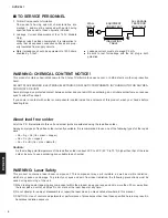
Page 2: ...Be sure to test for leakage with the AC plug in both polarities TO SERVICE PERSONNEL All of the P C B s installed in this unit and solder joints are soldered using the lead free solder Among some types of lead free solder currently available it is recommended to use one of the following types for the repair work Sn Ag Cu tin silver copper Sn Cu tin copper Sn Zn Bi tin zinc bismuth Caution As the m...

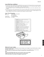
Page 3: ...ss instruction is provided elsewhere in this manual Adjustment of this control can increase the laser emission level from the device Laser Diode Properties Type Semiconductor laser GaAlAs Wave length 650 nm DVD 780 nm VCD CD Output power 7 mW DVD VCD CD Beam divergence 60 degrees Warning for power supply The primary side of the power supply carries live mains voltage when the player is connected t...

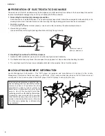
Page 4: ...e working environment Only attempt service after ensuring that all grounding procedures have been completed 1 Worktable grounding Put a grounded conductive material sheet or iron sheet on the area where the optical pickup is placed 2 Human body grounding Use an anti static wrist strap to discharge the static electricity from your body 2 Handling Precautions for DVD mechanism 1 Handle the DVD mecha...

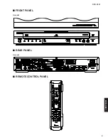
Page 5: ...DVD C961 5 DVD C961 FRONT PANEL U model REAR PANEL U model REMOTE CONTROL PANEL ...

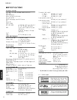
Page 6: ... Hz Playback Multistandard PAL NTSC HDMI video output 480 p 60 Hz 576 p 50 Hz 720 p 60 Hz 1080 i 60 Hz 1080 p 60 Hz CONNECTIONS Video output RCA Phono x 1 yellow S video output Mini DIN 4 pins x 1 Component video output Y output RCA Phono x 1 green PB output RCA Phono x 1 blue PR output RCA Phono x 1 red 2 channel audio output L R RCA Phono x 1 pair white red 6 channel audio output Audio front L R...

Page 7: ...ated logos are trademarks of DivX Inc and are used under li cense INTERNAL VIEW 8 9 0 7 1 2 3 4 5 6 1 2 3 4 5 6 7 8 9 0 POWER SUPPLY UNIT RS232C P C B DVD 5 DISC CHANGER MODULE FRONT 4 P C B HDMI P C B AV P C B MONO P C B FRONT 2 P C B FRONT 1 P C B FRONT 3 P C B Power supply unit Front side RS232C P C B OK NG Top view Switch Ref No 1107 Potentiometer Ref No VR1 REPAIR NOTES 1 DVD 5 disc changer m...

Page 8: ...rews 252 P C B to rear panel Remove 1500 and 1503 Fig 1 Remove P C B Power Supply Unit 1000 Open tray Fig 4 See How to manually open the tray ass y Remove CN1 CNA and CNB Fig 1 Remove 2 screws 257 P C B to bottom frame Release 2 spacers locking P C B to bottom frame Remove power supply unit RS232C P C B 1700 Open tray Fig 4 See How to manually open the tray ass y Remove screw 257 P C B to rear pan...

Page 9: ...iron to short circuit and unshort circuit laser diode After you have finished repairing remove the solder from the short circuit location When installing a new traverse unit remove the solder from the shorted point of P C B using an electrostatic shielding soldering iron How to manually open the tray ass y a Move the slider in the direction indicated with a flatblade screwdriver until the tray is ...

Page 10: ...GND 1 2 3 4 5 6 7 8 9 10 B01 GND B03 LED_Progressiv LED_HDMI LED_Downmix 5VL 5V_STBY IR GND 1 2 3 4 5 6 7 8 9 10 11 12 B02 GND Disc5_Y Disc4_Y Disc3_Y Disc2_Y Disc1_Y 5VL 5V_STBY SDA_uP GND SCL_uP 1 2 3 4 5 6 7 8 9 10 IR_SW RC6_IN RESET 5VL GND 24V 12VL 5V_STBY STBY_CTRL 1101 1300 B02 SCL SDA Keys 5V STBY 5V STBY DISC1 5_Y 7300 1100 7112 7111 7405 7101 1304 1000 1103 7201 1502 5601 MUTE MUTE SPDIF...

Page 11: ...6 I2C_CLK GND 8 9 SDA 7 20 2 10 GND_D 6 7 8 9 10 11 2 3 4 Y_REF 1 5VL 5VSTBY KEY_B02 Mic_det V CVBS AV_GND 2 C I2C_DATA To control LT 12 GND 11 2 7 8 9 AV_MUTE 19 18 17 16 1KHZ not used GND_D I2C_CLK I2C_DATA INTRQ 14 27M I2C_CLK 7 8 15 2 GND 1305 3 20 21 GND 5VL 12VL 24V 1 2 5VL LED_PROGRESSIVE I2C_CLK LED_DOWNMIX GND_B 3 4 5 1 2 10 11 12 5Vstby 12VL 5VL GND 24V 3 4 SubCen_PCM Cs_PCM GND 1 10 11 ...

Page 12: ...VERSE UNIT KHM313 MONO P C B Top view PRINTED CIRCUIT BOARDS FOR INFORMATION ONLY NO REPLACEMENT COMPONENT PARTS WILL BE AVAILABLE The first digit of a component indicates the component type 1xxx Connector 3xxx Resistor 5xxx Coil 7xxx IC Transistor FET 2xxx Capacitor 4xxx SMD jumper 6xxx Diode 9xxx Wire jumper ...

Page 13: ...1 13 The first digit of a component indicates the component type 1xxx Connector 3xxx Resistor 5xxx Coil 7xxx IC Transistor FET 2xxx Capacitor 4xxx SMD jumper 6xxx Diode 9xxx Wire jumper MONO P C B Bottom view ...

Page 14: ... P C B Bottom view MONO 1105 AV 1109 FRONT 3 1200 FRONT 2 1300 The first digit of a component indicates the component type 1xxx Connector 3xxx Resistor 5xxx Coil 7xxx IC Transistor FET 2xxx Capacitor 4xxx SMD jumper 6xxx Diode 9xxx Wire jumper ...

Page 15: ...T 1 1100 STANDBY ON DISC1 DISC2 DISC3 DISC4 DISC5 SA CD LED DVD AUDIO LED MULTI CH LED The first digit of a component indicates the component type 1xxx Connector 3xxx Resistor 5xxx Coil 7xxx IC Transistor FET 2xxx Capacitor 4xxx SMD jumper 6xxx Diode 9xxx Wire jumper ...

Page 16: ...101 PLAYXCHANGE STOP PLAY PAUSE NEXT PREV HDMI LED DOWN MIX LED AUDIO DIRECT LED OPEN CLOSE The first digit of a component indicates the component type 1xxx Connector 3xxx Resistor 5xxx Coil 7xxx IC Transistor FET 2xxx Capacitor 4xxx SMD jumper 6xxx Diode 9xxx Wire jumper ...

Page 17: ...10 AUDIO OUT DIGITAL OUT FRONT L R CENTER SUBWOOFER SURROUND L R MIXED 2CH L R COAXIAL OPTICAL The first digit of a component indicates the component type 1xxx Connector 3xxx Resistor 5xxx Coil 7xxx IC Transistor FET 2xxx Capacitor 4xxx SMD jumper 6xxx Diode 9xxx Wire jumper ...

Page 18: ...NT 1 1112 POWER SUPPLY UNIT CN3 MONO 1104 DVD 5 DISC CHANGER MODULE FRONT 4 1500 FRONT 4 1503 S VIDEO VIDEO HDMI 1302 VIDEO OUT The first digit of a component indicates the component type 1xxx Connector 3xxx Resistor 5xxx Coil 7xxx IC Transistor FET 2xxx Capacitor 4xxx SMD jumper 6xxx Diode 9xxx Wire jumper ...

Page 19: ...61 19 AV P C B Bottom view The first digit of a component indicates the component type 1xxx Connector 3xxx Resistor 5xxx Coil 7xxx IC Transistor FET 2xxx Capacitor 4xxx SMD jumper 6xxx Diode 9xxx Wire jumper ...

Page 20: ...ew AV 1104 AV 1102 MONO 1304 AV 1401 HDMI PR PB Y The first digit of a component indicates the component type 1xxx Connector 3xxx Resistor 5xxx Coil 7xxx IC Transistor FET 2xxx Capacitor 4xxx SMD jumper 6xxx Diode 9xxx Wire jumper ...

Page 21: ...1 21 HDMI P C B Bottom view The first digit of a component indicates the component type 1xxx Connector 3xxx Resistor 5xxx Coil 7xxx IC Transistor FET 2xxx Capacitor 4xxx SMD jumper 6xxx Diode 9xxx Wire jumper ...

Page 22: ... P C B Bottom view AV 1103 REMOTE CONTROL RS 232C OUT IN ON OFF The first digit of a component indicates the component type 1xxx Connector 3xxx Resistor 5xxx Coil 7xxx IC Transistor FET 2xxx Capacitor 4xxx SMD jumper 6xxx Diode 9xxx Wire jumper ...

Page 23: ... IOA5 57 IOA6 58 IOA7 59 HIGHA0 6 DVDRFIP IOA18 46 47 FG TDI 48 TMS 49 5 DVDD TCK 50 TDO 51 52 DVDD18_1 IOA2 39 4 DVDC PWMOUT1 40 TRO 41 FOO 42 USB_VSS 43 USBP 44 45 USBM USB_VDD3 31 TEO 32 TEZISLV 33 OP_OUT 34 OP_INN 35 OP_INP 36 37 DMO 38 FMO TROPENPWM 255 256 AVDD3 RFLVL 26 SGND 27 V2REFO 28 V20 29 DVDB 3 30 VREFO FEO RFGND 249 CSO 25 CEQP 250 CEQN 251 OSP 252 253 OSN 254 RFGC IREF 240 241 ADCV...

Page 24: ...7 3 6 22R 3305 3 4 5 T239 8 22R 3392 4 3393 1 22R 1 5322 BLM31 T232 T228 T231 100n 2321 3364 22R 100n 2309 3401 22R 1 2 22R 3345 3306 22R T203 BLM18P 5340 T202 2 7 T201 22R 3391 2 22R 3391 1 1 8 22R 3303 3 3 6 22R 4 5 5 3303 4 3394 4 22R 4 22R 3357 2304 100n 3335 75R T272 T209 T207 5342 BLM18P 22R 3408 3375 10K 2363 22p 22R 3344 3348 22R 20 U VA 6 VD 23 T205 RXP3 14 RXP4 15 RXP5 25 RXP6 26 SCL CCL...

Page 25: ...1 12 13 14 15 16 17 18 19 2 31 32 33 34 35 36 11 MT 131GNK 7100 1 10 7104 BC327 25 11 I138 GND 1 2 3 4 5 6 7 8 9 10 1110 09FMN SMT A TF GND 3107 22u 2R2 2104 33n 2101 I108 2126 47p 47p 2128 GND 2107 22u I140 I102 100n 2112 2 3 4 5 6 7 8 9 11 12 1112 10FMN SMT A TF 1 10 2116 33n GND BC847BW 7110 3129 1K0 2117 1n0 3130 10K BAS316 3131 10K 6100 GND 47p 2121 I183 3148 33R 22p GND 2109 3145 1K0 I154 VK...

Page 26: ...L 15u 5310 I300 I311 5VL I310 1306 5Vstby 330R 3326 3322 330R 3316 330R 5Vstby 330R 3318 GND 3327 10K I301 3301 10R 3306 330R 330R 3303 5Vstby 4310 3300 10R 7308 BC857BW LTL 816YE LTL 816YE 6303 LTL 816YE 6301 6302 6300 LTL 816YE BC857BW 7306 2K7 3328 3324 330R 330R 3320 7302 LTL 816YE BC857BW 3304 6306 330R 330R 330R 3305 3302 LTL 816YE 6304 10K 3325 3323 10K 1303 I306 I304 7301 BC857BW 10K 3317 ...

Page 27: ...10 I208 I209 5201 15u 220R 3204 BZX384 C6V8 6205 150R 3203 1205 GND_B 10K 2202 4203 GND RT 01T 1 0B 1250 1 1206 I206 330R 3210 6202 LTL 816GE 330R 3212 GND OUT 2 VS 270R 3205 7102 TSOP2236 3 GND 1 1251 RT 01T 1 0B 1 I207 2K7 3201 GND 1203 10K BC857BW 7202 2200 1 10 2 3 4 5 6 7 8 9 10FMN SMT A TF 1200 I205 I204 2201 100u I202 I203 100p 2210 1204 GND 5Vstby 5Vstby 5Vstby 5VL 3211 330R 6216 BZX384 C6...

Page 28: ... 10K 10K 3539 2505 1n0 7504 BC817 25 3544 1K0 I110 1K0 3541 3528 GND 10K 1K0 3540 3510 10K 1K0 3514 GND I124 GND I125 BC817 25 7506 BAS316 6501 1K0 3538 10K 3530 I106 1n0 2510 1n0 2509 I114 I115 GND 3 4 5 6 7 8 9 09FMN BTRK A 1503 1 2 I105 GND 1K0 3543 6502 BAS316 6503 BAS316 3503 1K0 GND GND BAS316 6500 I108 1n0 2503 I109 GND I102 1K0 3542 I103 I123 I122 GND I121 BC817 25 7512 GND GND 1n0 2511 1n...

Page 29: ... 7 8 100u 5601 2604 47p 4602 4603 4601 2601 100n 3601 150R 3603 10n 2605 33R 2603 47p 2 5600 600R 1600 YKC21 3416 1 3 GND 100n 2606 47p I601 4600 I600 I604 3602 I603 220R 100n 2602 GND 3 IN 1 VS 2 I602 DGND 7600 JFJ1000 010010 3600 DGND 5VD SPDIF_OUT No_used FRONT 4 Digital audio out FRONT 5 5 The first digit of a component indicates the component type 1xxx Connector 3xxx Resistor 5xxx Coil 7xxx I...

Page 30: ...RT 3 4 4 5 6 7 8 9 8V B9B EH A 1103 1 2 3 24V_Front GND I142 I153 GND 100R 3124 GND 3160 15R 3110 10K 8V 1K2 3114 LPR6520 N620F 1105 3 1 2 GND 2K2 3172 I119 GND GND I133 3107 1K2 3161 5K6 4100 5VSTDBY_Front 1K2 3136 BC847B 3142 7106 3138 1K5 1K0 8 GND MSP 801V1 02 01 B NI LF 1107 C 33R 3131 8V 3165 4105 3152 1K5 3109 1K2 GND 15R I103 GND GND 3155 220p 2107 BZX284 C15 6104 GND I158 2121 47p 2128 GN...

Page 31: ...60 BSN20 3 I227 1u0 2201 12VSTBY GND 3234 33R 22R 5201 4201 7211 BC847B 9 2210 100n 10 11 12 2 3 4 5 6 7 8 12FMN BTRK A 1200 1 4K7 3270 3242 6K8 3240 6K8 1K0 3285 4K7 3286 7216 BC857B BC847B 7215 4K7 3228 3229 1K0 4K7 3280 7209 BC857B 470R 3281 GND 1K0 3244 6K8 3227 GND I229 100R 3204 3230 2214 47u 33R GND 6203 BAS316 10V 100u 2215 GND 8VA 8VA 5VA GND VD 14 VLC 1 VLS VQ 17 I207 MUTEC2 18 MUTEC3 10...

Page 32: ...2313 4K7 3340 220R 3323 GND I309 16V 10u 2310 4 5 6 7 8 9 GND 16 17 18 19 2 20 21 22 3 1 10 11 12 13 14 15 1300 22FMN BTK A 3K3 3310 GND 1n0 2341 2315 100n 7300 1 LM833D 3 2 1 8 4 GND I308 I300 2344 8VA_B 680p 3327 2K7 GND I302 3n3 2355 3371 18K I301 180p 2336 3352 5K1 3350 5K1 18K 3375 3K9 3326 GND 1n0 2380 2K7 3315 3379 18K I305 GND I304 3346 220R GND AVCC_A GND 2314 180p 3 4 5 6 7 8 9 09FMN BTK...

Page 33: ...409 1402 B5B EH A 1 2K2 3420 GND 2403 16V 10u 5404 33u GND 8VA GND 100n 2452 4405 LD1117DT33 7405 1 3 IN 2 OUT 4403 BC847B 7403 1 3 2 2K2 3418 100n 2427 8V GND 2433 100n GND 2453 I414 I410 I411 I400 I409 3 4 5 6 7 8 9 1 10 11 12 13 2 1400 B13B PH K S LF SN 2407 2 3430 33R 7410 LD1086V33 1 3 6415 S1D GND 2410 100u 6410 6411 SS14 SS14 2411 2402 GND 100n GND GND 1R0 3417 5401 60R 3V3 15K 3414 3422 33...

Page 34: ...TAL_OUT 192 22R VDDcore5 96 VDDcore6 123 VDDcore7 138 VDDcore8 197 VSS1 9 VSS2 31 VSS3 49 VSS4 63 VSS5 89 VSS6 113 VSS7 129 VSS8 147 VSS9 194 VSScore1 17 VSScore2 37 VSScore3 69 TEST_IN 90 TEST_OUT0 116 TEST_OUT1 117 VDD1 8 VDD2 30 VDD3 48 VDD4 62 VDD5 88 VDD6 112 VDD7 128 146 VDD8 VDD9 193 VDDcore1 16 VDDcore2 36 VDDcore3 68 VDDcore4 80 SDRAM_DATA_31 87 SDRAM_DATA_4 54 SDRAM_DATA_5 55 SDRAM_DATA_...

Page 35: ...9 36 37 38 39 4 40 41 42 43 44 45 46 27 28 29 3 30 31 32 33 34 35 17 18 19 2 20 21 22 23 24 25 26 1 10 11 12 13 14 15 16 5VD AF7501 A2G1T 1004 3246 47R 3234 22R 3205 2K7 3254 47R F218 10n 2216 3281 5K6 F215 3244 47R DLINE_2 3292 10K 2228 4214 1 2 22p 22p 22R 2227 3235 22R 3299 3216 680R 3221 DPDET 10K 2 2215 100n 4215 1 1R0 3219 3273 4K7 7205 2210 100n AV BC847B 5205 30R 100n 2217 3243 47R 4200 1 ...

Page 36: ...5 G13 F316 G13 F317 E10 F329 G14 F330 B11 F331 C14 1R0 3314 4315 4307 4331 2335 22p 2302 22p AV 5 2 AV 4328 AD8061ART 7310 3 4 1 2361 100n 2331 47u 30R 5321 22p 2332 AV F325 3303 1K2 5310 30R 5302 30R 1K2 3335 F307 4314 30R 5301 C F331 5 2 1303 310310126941 AD8061ART 3 4 1 100p 2319 7303 AV 1 3V3D F326 1003 1 2 100u 2314 YKC21 3930 2360 220u AV AV 4305 5300 4u7 F303 10 11 2 3 4 5 6 7 8 9 HFW11S 2S...

Page 37: ...n 2429 10 11 2 3 4 5 6 7 8 11FMN SMT A TF 1401 1 4406 3450 120R 1 3413 22R F415 10K 3485 10p 2417 3494 22R 2415 22u 6 3V 47R F416 3455 3439 47R 100n 2406 1 120R 3451 47R 3437 3452 390R 1 5408 30R 2448 100n 2410 1n0 3447 47K 3430 47R 22R 3406 100n 2425 2409 100n 5407 30R 22R 3410 2401 100n 2419 100n 47R 3426 47R 3425 1 3 2 LM317MDT 7407 F420 100n 2421 3461 6 7 8 9 100R 1402 S7B PH SM4 TB LF 1 2 3 4...

Page 38: ...35 8 4 18 5 1 2 3 22 23 24 25 26 27 28 29 30 31 32 41 42 43 52 53 54 55 56 20 21 60 61 62 63 64 36 37 38 39 40 48 49 50 51 9 6 7 57 58 59 11 12 13 14 15 16 17 44 45 46 47 Φ MC TMP86FS49FG 7105 19 10 1108 B2B PH K 1 2 5107 2K7 2116 5 6 7 8 47u 16V 1103 B8B EH A 1 2 3 4 3130 10K 10K 3133 2120 2115 10p 10p 1 4 3 2 7103 SFH615 I103 2112 33n 2106 22p 3135 33R 33R 3125 100n 2108 2 4102 1101 1 10 33R 313...

Page 39: ...DVD C961 39 MEMO MEMO MEMO MEMO ...

Page 40: ...8103 8502 8505 8506 8508 8600 8601 8602 8603 8606 8607 257 257 333 336 338 Bracket Front CM Unit Tray ass y Solder P C B Traverse unit 1 7 mm T6 2 7 mm T10 When disassembling use the special screw driver with tip shape in figure Note for replacement of the traverse unit P C B of a new traverse unit is shorted When installing a new traverse unit remove the solder from the shorted point of P C B usi...

Page 41: ...HDMI 3139 248 52831 8102 AAX59280 FLEXIBLE FLAT CABLE 12P 280mm P 1mm 3139 241 00771 8103 AAX59260 FLEXIBLE FLAT CABLE 10P 340mm P 1mm 3139 241 00651 8500 AAX64690 FLEXIBLE FLAT CABLE 10P 560mm P 1mm 3139 241 00871 8502 AAX59220 FLEXIBLE FLAT CABLE 22P 180mm P 1mm 3139 110 35631 8505 AAX64670 FLEXIBLE FLAT CABLE 13P 220mm P 1mm 3139 111 02411 8506 AAX83990 FLEXIBLE FLAT CABLE 11P 100mm P 1mm 3139 ...

Reviews: