background image

EAD10 Reference Manual (Advanced)

1

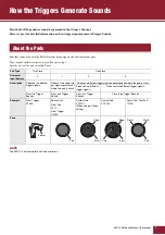
How the Triggers Generate Sounds ........................ 2

About the Pads.......................................................... 2

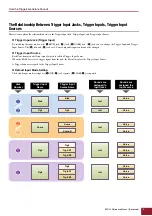
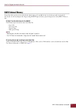
The Relationship Between Trigger Input Jacks, 

Trigger Inputs, Trigger Input Sources ............. 3

Trigger Sound (Instrument, Voice) ....................... 4
EAD10 Internal Memory....................................... 5

MENU.......................................................................... 6

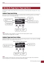
Basic Screen Operations .......................................... 6
Selecting the Trigger Input or Trigger Input Source .. 7
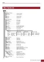
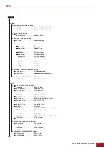
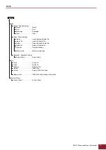
Menu  Function List................................................... 8

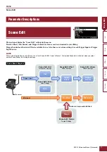
Parameter Descriptions........................................... 11

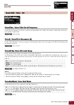
Scene Edit.......................................................... 11

Trigger ................................................................ 25

Utility .................................................................. 32

Job ..................................................................... 39

File ..................................................................... 47

Factory Reset ..................................................... 57

Connecting a Computer.......................................... 59

Installing the Yamaha Steinberg USB Driver .......... 59
Using DAW Software............................................... 60
Yamaha USB-MIDI Driver ....................................... 60

With the EAD10 Reference Manual (Advanced) (this document), you can click on an item you want to dis-
play with the link function or use the term search function.

When you click on any of the tabs on the right side of the page, you will be taken to the first page of the cor-
responding section.

Contents

How to Use This Manual
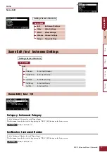
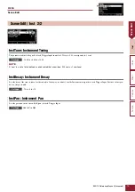
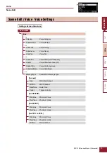
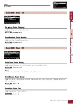
Scene Edit

Inst

Effect

V

oice

Reference Manual 

(Advanced)

Electronic Acoustic 
Drum Module

EN

Summary of Contents for EAD10

Page 1: ...gger 25 Utility 32 Job 39 File 47 Factory Reset 57 Connecting a Computer 59 Installing the Yamaha Steinberg USB Driver 59 Using DAW Software 60 Yamaha USB MIDI Driver 60 With the EAD10 Reference Manua...

Page 2: ...escription Produces two different trigger signals Produces the same trig ger signal regardless of where the pad is struck Produces a different trigger signal depending upon where the pad is struck Pro...

Page 3: ...changed Trigger Input Source Each Zone transmits a different signal which is called a Trigger Input Source When the EAD10 receives a trigger signal from the pad the Main Unit plays the Trigger Input S...

Page 4: ...the EAD10 you can use a different Voice for each Trigger Input Source For example on an acoustic snare drum you can play a head shot sound open rim shot sound and a closed rim shot sound all from the...

Page 5: ...tings Data That Can Be Saved in the EAD10 The following types of data can be stored in the Main Unit Scene 200 Wave Up to 100 Trigger Settings Other general settings Saving Save and Loading Load Data...

Page 6: ...he screen appears when you press the MENU button Navigating the MENU Changing the Setting Values Basic Screen Operations F1 and F2 move the cursor up and down ENTER F3 opens the screen Changes the val...

Page 7: ...t Source When the Input Mode is paired selecting Trg2 or Trg4 does not affect the settings nor generate any triggers In MENU Trigger Pad Type FootSW is not displayed When the Input Mode is paired sele...

Page 8: ...iggerRevSend Trigger Sound Reverb Send Voice RevSend Trigger Sound Voice Reverb Send MicEffType Mic Effect Type MicEffDepth Mic Effect Depth TrgEffType Trigger Sound Effect Type TrgEffSend Trigger Sou...

Page 9: ...n Level Reject Lvl Rejection Level Source Pad FootSwSelect Foot Switch Select Settings FootSwSelect Select Foot Switch Utility General General Utility Settings SceneKnob Scene Knob AutoPowerOff Auto P...

Page 10: ...port All Audio Files Delete Delete Selected Audio File Delete All Delete All Audio Files Optimize Optimize Memory Memory Info Memory Information Recorder Recorder Settings Export Audio Export Audio Fi...

Page 11: ...customizing the Scene save Store it as a User Scene EAD10 Owner s Manual Customized Scene data will be lost when you select another Scene without first storing the settings NOTE Scene Block Diagram T...

Page 12: ...n also be selected by pressing the TRG F3 button on the Scene screen Refer to the Data List Settings Screen Structure Scene Edit Inst Instrument Settings Voice Voice Settings Effect Effect Settings Vo...

Page 13: ...the time it takes for the sound to fade away to silence for the Instrument assigned to each Trigger Input Positive values pro duce a crisper sound 10 to 0 to 10 InstPan Instrument Pan Sets the positi...

Page 14: ...off Frequency VoiceQ Voice Filter Resonance Q VoiceAltGrp Voice Alternate Group VoiceHoldMode Voice Hold Mode 4 4 MessageType Select MIDI Message Type For note Note MIDI Note Output MIDI Ch MIDI Chann...

Page 15: ...orresponds to 10 cents 24 0 to 0 0 to 24 0 VoiceDecay Voice Decay Sets the decay the time it takes for the voice to fade away to silence for the Voice assigned to each Trigger Input Source Positive va...

Page 16: ...dMode Voice Hold Mode Sets the hold mode for the Voice produced by each Trigger Input Source on off Scene Edit Voice 3 4 Settings Settings Off Voice is not assigned to an alternate group HHOpen Hi Hat...

Page 17: ...Scene Edit Scene Edit Voice 4 4 When note is selected for MessageType When REVERB is selected for MessageType When EFFECT is selected for MessageType When CC01 to CC95 is selected for MessageType Sce...

Page 18: ...igger Input for each Trigger Input Source TrgVel Trigger Velocity Sets the velocity value of the MIDI signal that is sent whenever a Trigger Input is received from a Trigger Input Source For REVERB Co...

Page 19: ...ding to how the pedal pressed or how hard the pad is struck No sound is produced even when the pad is struck MinValue Minimum Value Sets the minimum value used when the pedal is released or when the p...

Page 20: ...ttings Screen Structure Scene Edit Effect 1 4 ReverbType Reverb Type ReverbSend Reverb Send RevReturn Reverb Return 2 4 Mic RevSend Mic Reverb Send TriggerRevSend Trigger Sound Reverb Send Voice RevSe...

Page 21: ...b RevReturn Reverb Return Sets how much of the sound is returned from the Return effect Return Level 0 to 127 Mic RevSend Mic Reverb Send Sets how much of the sound is sent from the Mic Sound after ap...

Page 22: ...s the type of Effect to be applied to the Trigger Sound Refer to the Data List TrgEffSend Trigger Sound Effect Send and Dry Balance Specifies the balance between the Trigger Sound to be sent to the Ef...

Page 23: ...er Sound within the same Scene 0 to 127 Scene Edit Volume Volume Settings Scene Trigger Inst Inst Trigger Mic Voice Voice Voice Voice Voice Volume Voice Volume Voice Volume Voice Volume Inst Volume In...

Page 24: ...Voice Volume Trigger Sound Voice Volume Sets the volume of the Voice for each Trigger Input Source Use this parameter to adjust the balance between Zones in the same Instrument 0 to 127 Tempo Tempo fo...

Page 25: ...Mode Sets the qKICK w jack to use the qKICK and w Trigger Inputs as a set or used separately Trg3 Trg4 Trigger 3 Trigger 4 Input Mode Sets whether the eSNARE r jack eSNARE and r Trigger Inputs will be...

Page 26: ...5 Spl21 to Spl25 ofs1 to ofs5 Trigger Curve Curve Settings Settings Screen Structure Trigger Curve Velocity Curve Velocity Curve Settings ofs3 ofs4 ofs5 ofs2 ofs1 n o r m l o u d 1 h a r d 1 h a r d 2...

Page 27: ...2 4 Gain Gain Sensitivity Sensitivity RejectTime Reject Time 3 4 MinLevel Minimum Level MaxLevel Maximum Level MinVelocity Minimum Velocity MaxVelocity Maximum Velocity 4 4 WaitTime Wait Time RimGain...

Page 28: ...the like and named them accordingly These groupings of parameters are referred to as pad types Given that pads come in many different varieties such as kicks snares toms cymbals and drum triggers it...

Page 29: ...wn below Minimum level 0 to 99 Maximum level 1 to 100 MinVelocity Minimum Velocity MaxVelocity Maximum Velocity These parameters set the minimum and maximum velocities corresponding to the MinLevel Ma...

Page 30: ...to the mono 2 input jack This parameter is only effective when the input mode is set to paired 1 to 127 H R Balance H R Balance It sets the balance between the two piezo head and rim H49 to H1 0 R1 t...

Page 31: ...Trg 4 Trg 5 Trg 6 FootSwSelect Select Foot Switch Choose from HH65 hi hat controller FC3 foot pedal FC4 5 foot pedal or foot switch or FC7 foot controller for the controller con nected to the FOOT SW...

Page 32: ...s Settings Screen Structure Utility General 1 4 SceneKnob Scene Knob AutoPowerOff Auto Power Off LCD Contrast LCD Contrast 2 4 ClickOutput Click Output Destination ClickCountOff Click Count off L R Vo...

Page 33: ...is turned off by the Auto Power Off function or set to off to disable the Auto Power Off function off 5 10 15 30 60 120 min LCD Contrast LCD Contrast Adjusts the contrast on the screen 0 to 63 Utility...

Page 34: ...o a fixed value so that you can adjust only the Headphone volume with the MASTER VOLUME knob When set to variable you can adjust the Headphone volume and the external output volume with the MAS TER VO...

Page 35: ...data The auto setting switches settings automatically so that only MIDI data is exchanged when using the recorder and audio and MIDI are exchanged at all other times The recorder is disabled when set...

Page 36: ...volume for the signal received via the AUX IN jack USB Volume USB Audio or Recorder Playback Volume Sets the volume for the USB audio input or Recorder playback ClickVolume Click Volume Sets the Click...

Page 37: ...ff Switches the Click on and off bypassOn Off Switches the bypass on and off Useful for switching Effect or Trigger effects on and off while playing To bypass use the BypassSW Bypass Switch REVERB Con...

Page 38: ...affect audio received from the AUX IN jack EQ LowGain EQ Low Gain EQ HighGain EQ High Gain 12 to 0 to 12 Utility PadFunction 2 2 Rev Applies Reverb or not Eff Applies the Effect or not Trg1 to Trg6 Pl...

Page 39: ...ed using the Recall function 1 Press the RECALL button F3 and the confirmation screen appears 2 Press the YES button F1 to Recall the data Completed appears when Recall is complete and the screen retu...

Page 40: ...ton F3 to select the Scene that you want to move 3 Press the and buttons F1 and F2 or the and buttons to move the selected Scene 4 After moving the Scene to the position where you want it press the IN...

Page 41: ...Scenes Completed appears when the Exchange is complete and the screen returns to the Exchange screen Clear Clear Initialize the Scene 1 Use the and buttons to select the Scene you want to initialize...

Page 42: ...nment will be made When you have assigned the imported Wave to a Trigger Input Source perform the Scene store operation Job Wave Wave Settings Settings Screen Structure Job Wave 1 2 Import Import Sele...

Page 43: ...button F3 and the confirmation screen appears 2 Press the YES button F1 to Import Press the NO button F3 to cancel the Import and the screen returns to Step 1 Press the CANCEL button F3 during Import...

Page 44: ...to Step 1 Completed appears when the Delete is complete and the screen returns to the Delete Screen Delete All Delete All Audio Files Deletes all Waves from the internal Wave memory of the EAD10 1 Pr...

Page 45: ...reen returns to Step 1 Completed appears when Optimization is complete and the screen returns to the Optimize screen Memory Info Memory Information Displays the usage of the Wave memory of the EAD10 P...

Page 46: ...d appears when the export is complete and the screen returns to the Export screen Job Recorder Recorder Settings Settings Screen Structure Job Recorder Export Audio Export Audio Procedure Entering the...

Page 47: ...a bin extension which is not displayed on the EAD10 Screen File size This refers to the size of the file The file size is determined by the amount of data saved in the file File size is measured in u...

Page 48: ...the Scene contains User Waves the User Waves are also saved File 1 2 Save Save File Procedure All All data all Scenes all Waves Utility data and Trigger settings AllScene Scene data for all Scenes One...

Page 49: ...een returns to Step 2 If a file with the same file name already exists the overwrite confirmation screen as shown below appears To save under a different file name press the NO button F3 and the scree...

Page 50: ...a computer for file management make sure to move the files back to the root directory of the USB flash drive 1 Connect the USB flash drive containing the files saved with the EAD10 into the USB TO DE...

Page 51: ...ins User Waves the User Waves are also loaded 5 Press the LOAD button F3 The File Load confirmation screen appears 6 Press the YES button F1 to load A message similar to that shown below appears durin...

Page 52: ...the file to be renamed 5 Set a new name for the file Press the button F2 to move the cursor to the bottom of the screen Press the Name button F2 to display the Enter File Name screen Rename Rename Fi...

Page 53: ...drive 1 Connect the USB flash drive containing the saved file you want to delete using the EAD10 into the USB TO DEVICE terminal 2 Navigate to MENU File Delete The following screen appears NOTICE Do...

Page 54: ...ress the DELETE button F3 The Delete confirmation screen appears 7 Press the YES button F1 to delete the file Completed appears when the Delete process is complete and the screen returns to Step 2 All...

Page 55: ...drive into the USB TO DEVICE terminal 2 Navigate to MENU File Format The following screen appears 3 Press the FORMAT button F3 The Format USB flash drive confirmation screen appears Format Format USB...

Page 56: ...flash drive is being formatted Doing so may cause the EAD10 to malfunction or corrupt memory in the USB flash drive File 2 2 Memory Info USB Flash Drive Memory Information Total Total memory size MB D...

Page 57: ...ory reset confirmation screen appears 3 Press the YES button F1 to carry out the Factory Reset If you do not want to carry out the Factory Reset press the NO button F3 Settings Screen Structure Factor...

Page 58: ...D10 Reference Manual Advanced 58 Factory Reset The following message appears during the operation Completed appears when the Factory Reset is complete and the screen returns to the Scene screen Factor...

Page 59: ...l USB cable Main Unit NOTE Precautions when using the USB TO HOST terminal When connecting the computer to the USB TO HOST terminal make sure to observe the following points Failing to do so risks fre...

Page 60: ...rresponds to your operating system For instructions on installing the driver refer to the Installation Guide included with the download file Information on system requirements is provided on the above...

Reviews: