background image

SERVICE MANUAL

This manual has been provided for the use of authorized YAMAHA Retailers and their service personnel.
It has been assumed that basic service procedures inherent to the industry, and more specifically YAMAHA Products, are already
known and understood by the users, and have therefore not been restated.

WARNING:

Failure to follow appropriate service and safety procedures when servicing this product  may result in personal
injury, destruction of expensive components, and failure of the  product to perform as specified. For these reasons,
we advise all YAMAHA product owners that any service required should be performed by an authorized YAMAHA
Retailer or the appointed service representative.

IMPORTANT:

The presentation or sale of this manual to any individual or firm does not constitute authorization,  certification  or
recognition  of  any  applicable  technical  capabilities,  or establish a principle-agent relationship of any form.

The data provided is believed to be accurate and applicable to the unit(s) indicated on the cover.  The research, engineering, and service
departments of YAMAHA are continually striving  to improve YAMAHA products. Modifications are, therefore, inevitable and
specifications are subject to change without notice or obligation to retrofit. Should any discrepancy appear to exist, please contact the
distributor's Service Division.

WARNING:

Static discharges can destroy expensive components. Discharge any static electricity your body may have
accumulated by grounding yourself to the ground buss in the unit (heavy gauge black wires connect to this buss).

IMPORTANT:

Turn the unit OFF during disassembly and part replacement. Recheck all work before you apply power to the unit.

IMPORTANT NOTICE

1 0 1 0 0 0

SERVICE MANUAL

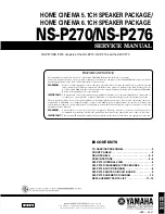
NS-P270/NS-P276

HOME CINEMA 5.1CH SPEAKER PACKAGE/
HOME CINEMA 6.1CH SPEAKER PACKAGE

NS-P270/NS-P276 consists of the NX-E270, NX-C270 and the SW-P270

■ 

CONTENTS

TO SERVICE PERSONNEL  . . . . . . . . . . . . . . . . . . . . 2
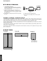
FRONT PANELS  . . . . . . . . . . . . . . . . . . . . . . . . . . . . . 2
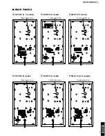
REAR PANELS  . . . . . . . . . . . . . . . . . . . . . . . . . . . . 3–4
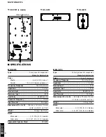
SPECIFICATIONS  . . . . . . . . . . . . . . . . . . . . . . . . . . 4–6
SW-P270 INTERNAL VIEW  . . . . . . . . . . . . . . . . . . . . 6
SW-P270 DISASSEMBLY PROCEDURES  . . . . . . . . 7
SW-P270 BLOCK DIAGRAM  . . . . . . . . . . . . . . . . . . . 8
SW-P270 PRINTED CIRCUIT BOARD  . . . . . . . . . . . . 9
SW-P270 SCHEMATIC DIAGRAM  . . . . . . . . . . . . . . 10
REPLACEMENT PARTS LIST  . . . . . . . . . . . . . . 11–15

NS-P270

NS-P276

© 2006                                          All rights reserved.

This manual is copyrighted by YAMAHA and may not be copied or

redistributed either in print or electronically without permission.

‘06. 01

Summary of Contents for NS-P270

Page 1: ...and service departments of YAMAHA are continually striving to improve YAMAHA products Modifications are therefore inevitable and specifications are subject to change without notice or obligation to retrofit Should any discrepancy appear to exist please contact the distributor s Service Division WARNING Static discharges can destroy expensive components Discharge any static electricity your body ma...

Page 2: ...OTICE The solder used in the production of this product contains LEAD In addition other electrical electronic and or plastic where applicable components may also contain traces of chemicals found by the California Health and Welfare Agency and possibly other entities to cause cancer and or birth defects or other reproductive harm DO NOT PLACE SOLDER ELECTRICAL ELECTRONIC OR PLASTIC COMPONENTS IN Y...

Page 3: ...76 3 NS P270 NS P276 SW P270 U C models SW P270 T model SW P270 R model SW P270 A model SW P270 B G models SW P270 K model REAR PANELS POWER INDICATOR POWER INDICATOR POWER INDICATOR POWER INDICATOR POWER INDICATOR POWER INDICATOR ...

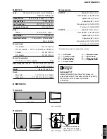
Page 4: ...05 mm x 151 mm x 113 mm 4 1 8 x 5 15 16 x 4 7 16 Weight 0 8 kg 1 lbs 12 oz Finish Black color U C R A B G L models Silver color U C R T K A B G L models Appropriate Speaker Stand SPS 80S NX C270 Type Full range acoustic suspension Magnetic shielding type Driver 5 cm 2 cone x 2 Frequency Response 130 Hz to 20 kHz Impedance 6 ohms Nominal Input 30 W Maximum Input 100 W Sensitivity 85 dB 2 83 V m Inp...

Page 5: ...ht 8 5 kg 18 lbs 12 oz Finish Black color U C R A B G L models Silver color U C R T K A B G L models Accessories NS P270 Subwoofer cable 3m x 1 Nonskid pad x 4 for SW P270 Speaker cable 10 m x 2 Speaker cable 4 m x 3 Nonskid pad x 16 for NX E270 Fastener x 2 for NX C270 NS P276 Subwoofer cable 3m x 1 Nonskid pad x 4 for SW P270 Speaker cable 10 m x 3 Speaker cable 4 m x 3 Nonskid pad x 24 for NX E...

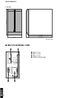
Page 6: ...NS P270 NS P276 6 NS P270 NS P276 SW P270 200 7 7 8 370 14 9 16 335 13 3 16 365 14 3 8 Unit mm inch SW P270 INTERNAL VIEW 2 1 4 3 q MAIN 2 P C B w MAIN 1 P C B e MAIN 3 P C B r POWER TRANSFORMER ...

Page 7: ...hen installing the Front Grille Ass y apply quick drying bond to the dowels and then fit them into dowel holes for secure installation The Front Grille Ass y will come off easily if its dowels are fitted into dowel holes only 2 Removal of Rear Panel Ass y Remove 14 screws 1 Fig 2 Arrow marks are printed to identify the screws to be removed When assembling the Rear Panel Ass y check to ensure that ...

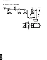
Page 8: ...7A VR1 VOLUME L P F 6dB oct H P F 12dB oct L P F 12dB oct 6 5 7 5 7 IC7B IC4 Q10 11 12 13 A N I C LIMITER RY1 3 1 2 IC2 Q9 D14 15 16 Q3 4 5 8 D9 10 11 12 1 10 B B 9 8 0 1 PROTECTION 12 B B 12 REGULATOR POWER SUPPLY D3 Q1 D6 Q2 D7 F2 POWER SW2 DRIVER INPUT POWER AMP ...

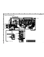
Page 9: ...T BOARD P C B MAIN 2 P C B MAIN 1 P C B MAIN 3 POWER CABLE POWER DRIVER WH BE INPUT VOLUME POWER INDICATOR WH BE R T K L models R T K L models 3 1 6 7 8 2 4 5 1 8 2 U C A B G models 1 4 BR BL 110 120V 220 240V WH SW1 RE GR 2 5 3 6 Circoic No U C R T K A B G L F1 SW1 C50 ...

Page 10: ...0 INPUT MAIN 2 MAIN 3 POWER U C A B G models R T K L models MAIN 1 DRIVER VOLUME POWER INDICATOR IC4 STK404 050 Power Amp 1 1 2 3 4 5 6 7 8 9 10 R1 R4 R5 C1 C2 D1 TR3 TR5 R3 R6 TR4 SUB R2 TR1 TR2 TR6 TR7 TR8 IC1 2 7 KIA4558P Dual OP Amp OUT1 IN1 VCC VCC OUT2 1 2 3 4 5 IN1 IN2 IN2 6 7 8 SW P270 SCHEMATIC DIAGRAM All voltages are measured with a 10MΩ V DC electronic volt meter Components having spec...

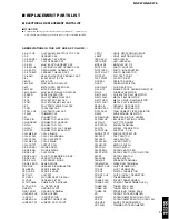
Page 11: ... L DTCT LIGHT DETECTING MODULE L EMIT LIGHT EMITTING MODULE LED DSPLY LED DISPLAY LED INFRD LED INFRARED MODUL RF MODULATOR RF PHOT CPL PHOTO COUPLER PHOT INTR PHOTO INTERRUPTER PHOT RFLCT PHOTO REFLECTOR PIN TEST PIN TEST POINT PLST RIVET PLASTIC RIVET R ARRAY RESISTOR ARRAY R CAR CARBON RESISTOR R CAR CHP CHIP RESISTOR R CAR FP FLAME PROOF CARBON RESISTOR R FUS FUSABLE RESISTOR R MTL CHP CHIP ME...

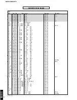
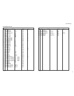
Page 12: ...0 C MYLAR 0 82uF 50V J 352307 C20 21 UR867220 C EL 22uF 50V 356201 C22 UR838100 C EL 100uF 16V 353103 C24 UR838100 C EL 100uF 16V 353103 C25 AAX76110 C EL BP 22uF 16V 066625 C26 27 UR837470 C EL 47uF 16V 338563 C28 UA655470 C MYLAR 0 47uF 50V J 352302 C29 AAX09530 C CE 100pF 50V 065382 UCRTAL C29 AAX76230 C CE 470pF 50V 065425 KBG C30 UA654100 C MYLAR 0 01uF 50V 352288 C31 AAX42490 C POL 2200pF 50...

Page 13: ...4W 044149 R19 AAX76420 R MTL OXD 330Ω 2W 358070 R33 VH005800 R MTL FLM 2 7KΩ 1 4W 068203 R35 AAX11860 R CAR FP 100Ω 1 4W 044153 R37 AAX11880 R CAR FP 1KΩ 1 4W 044454 R40 VP441400 R MTL FLM 10KΩ 1 4W 068279 R41 AAX09780 R MTL FLM 20KΩ 1 4W 068187 R42 VP441400 R MTL FLM 10KΩ 1 4W 068279 R43 VH009600 R MTL FLM 100KΩ 1 4W 068149 R46 AAX11860 R CAR FP 100Ω 1 4W 044153 R47 VP441400 R MTL FLM 10KΩ 1 4W 0...

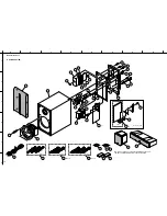
Page 14: ...21 1 3 17 17 32 12 15 15 30 7 26 18 11 9 23 24 21 22 25 22 8 18 19 19 6 13 14 14 2 1 6 2 6 10 25 3 10 m x 3 204 NS P276 NX E270 and NX C270 requires replacement as a unit Individual replacement parts will not be supplied 28 28 27 27 10 m x 2 203 NS P270 4 m x 3 202 23 6 20 R T K L models SW 1 1 ...

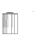
Page 15: ...72860 POWER CABLE 2m 389588 B Z 8 V8366400 POWER CABLE 2m 355106 GL 9 CB072750 CORD STOPPER SR 4N 4 078569 10 AAX31050 COVER 352528 11 AAX76290 REAR PANEL 435577 UC 11 AAX76300 REAR PANEL 435578 RTKL 11 AAX76310 REAR PANEL 435579 A 11 AAX76320 REAR PANEL 435580 BG 12 AAX51750 MOLD COVER 331822 13 AAX51530 CUSHION 18x90 363196 14 AAX51520 CUSHION 3x120 331840 15 AAX51510 CUSHION 3x50 078825 17 AAX3...

Page 16: ...NS P270 NS P276 16 NS P270 NS P276 MEMO ...

Reviews: