background image

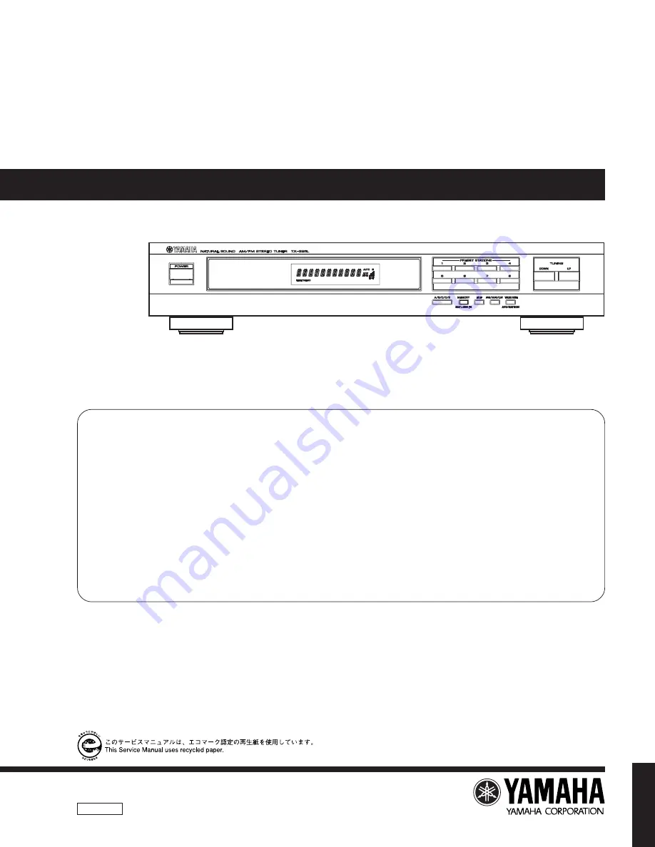
TX-396L

SERVICE  MANUAL

AM/FM STEREO TUNER

TX-396L

The data provided is believed to be accurate and applicable to the unit(s)
indicated on the cover.  The research, engineering, and service departments
of YAMAHA are continually striving to improve YAMAHA products.
Modifications are, therefore, inevitable and specifications are subject to
change without notice or obligation to retrofit.  Should any discrepancy
appear to exist, please contact the distributor's Service Division.

WARNING:

Static discharges can destroy expensive components.
Discharge any static electricity your body may have
accumulated by grounding yourself to the ground buss in
the unit (heavy gauge black wires connect to this buss).

IMPORTANT:

Turn the unit OFF during disassembly and part
replacement.  Recheck all work before you apply power
to the unit.

1 0 0 7 0 0

CONTENTS

TO SERVICE PERSONNEL

..........................................

1

SPECIFICATIONS

..........................................................

1

INTERNAL VIEW ...........................................................

2

REAR PANELS ..............................................................

2

DISASSEMBLY PROCEDURES

................................... 2

ADJUSTMENTS

......................................................... 3~7

µ

COM DATA

.................................................................. 8

DISPLAY DATA

............................................................. 9

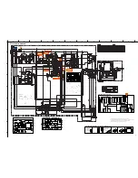
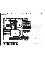
BLOCK DIAGRAM

................................................. 10~11

PRINTED CIRCUIT BOARD

.................................. 12~13

SCHEMATIC DIAGRAM

........................................ 14~15

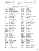
PARTS LIST

........................................................... 16~21

This manual has been provided for the use of authorized YAMAHA
Retailers and their service personnel.
It has been assumed that basic service procedures inherent to the industry,
and more specifically YAMAHA Products, are already known and
understood by the users, and have therefore not been restated.

WARNING:

Failure to follow appropriate service and safety
procedures when servicing this product may result in
personal injury, destruction of expensive components,
and failure of the product to perform as specified.  For
these reasons, we advise all YAMAHA product owners
that any service required should be performed by an
authorized YAMAHA Retailer or the appointed service
representative.

IMPORTANT:

The presentation or sale of this manual to any individual
or firm does not constitute authorization, certification or
recognition of any applicable technical capabilities, or
establish a principle-agent relationship of any form.

IMPORTANT NOTICE

TX-396L

P.O.Box 1, Hamamatsu, Japan

Summary of Contents for TX-396L

Page 1: ...PROCEDURES 2 ADJUSTMENTS 3 7 µCOM DATA 8 DISPLAY DATA 9 BLOCK DIAGRAM 10 11 PRINTED CIRCUIT BOARD 12 13 SCHEMATIC DIAGRAM 14 15 PARTS LIST 16 21 This manual has been provided for the use of authorized YAMAHA Retailers and their service personnel It has been assumed that basic service procedures inherent to the industry and more specifically YAMAHA Products are already known and understood by the u...

Page 2: ... with solder or components located inside the enclosure of this product wash your hands before handling food SPECIFICATIONS FM SECTION Tuning Range 87 50 to 108 00 MHz 50dB Quieting Sensitivity IHF Mono 1 55 µV 15 1 dBf Stereo 1 kHz 100 MOD 21 µV 37 7 dBf Usable Sensitivity DIN Mono S N 26 dB 0 9 µV Stereo S N 46 dB 24 µV Alternate Channel Selectivity Selectivity two signals 40 kHz Dev 300 kHz 70 ...

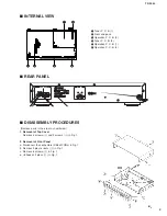
Page 3: ...on P C B 1 6 Operation P C B 3 DISASSEMBLY PROCEDURES Remove parts in the order as numbered 1 Removal of Top Cover Remove 4 screws 1 and 2 screws 2 in Fig 1 2 Removal of Front Panel a Disconnect the connectors CB3 anf CB4 in Fig 1 b Remove 2 plastic rivets 3 in Fig 1 c Remove 5 screws 4 in Fig 1 d Unhook at 2 place 5 in Fig 1 ...

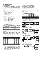
Page 4: ...ows Test points Rating or Standard 5 V terminal 5 6 0 5 V VP terminal 23 0 1 0 V CAUTION Before setting to the TEST mode write down the user preset memory content in the table as shown below This is because setting to the TEST mode will cause the memory content to be the factory preset memory content i e all the user preset memory content will be erased User preset memory content Preset keys P1 P2...

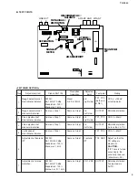
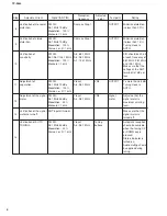
Page 5: ...dBµ Modulation 100 Monaural 1 kHz Same as Step 1 Same as Step 1 Same as Step 1 Same as Step 1 FM SG 98 1 MHz 30 dBµ Modulation 100 Monaural 1 kHz FM SG 98 1 MHz 70 dBµ Modulation 100 Stereo L or R 1 kHz Adjusted point L8 right side L8 left side L8 right side L8 left side Frontend IFT VR1 VR2 Reception frequency Preset A 4 98 1 MHz Same as Step 1 Same as Step 1 Same as Step 1 Same as Step 1 Same as...

Page 6: ...Modulation 30 Stereo L or R 1 kHz Adjusted point VR4 VR3 Tuning buttons Reception frequency Same as Step 1 Same as Step 1 A 6 88 1 MHz A 4 98 1 MHz A 7 106 1 MHz Preset A 4 98 1 MHz Preset A 4 98 1 MHz Preset A 4 98 1 MHz Rating Minimize distortion to less than 0 7 Minimize distortion to less than 1 4 Tuning mode is AUTO S N should be 30 dB at each frequency of 88 1 MHz 98 1 MHz and 106 1 MHz Make...

Page 7: ...440 kHz 50 dBµ 1 kHz 30 modulation AM SG 1080 kHz 90 dBµ ANT input 90 dBµ ANT input 10 dBµ or less AM SG 1080 kHz 60 dBµ 1 kHz 30 modulation Adjusted point L5 Tuning button Reception frequency Preset B 1 630 kHz Preset B 1 630 kHz B 2 1080 kHz B 3 1440 kHz Preset B 2 1080 kHz Preset B 2 1080 kHz Rating Maximize detected signal output To be less than 54 dBµ Make sure that the signal meter is turned...

Page 8: ...dBµ 1 kHz 30 modulation Adjusted point Tuning button Reception frequency Preset C 2 171 kHz C 3 225 kHz C 4 270 kHz Preset B 2 225 kHz Preset B 2 225 kHz Rating To be less than 66 dBµ Make sure that the signal meter is turned on Make sure that the signal meter is turned off Automatic reception should be available when the tuning UP or DOWN key is pressed Audio muting should be applied during tunin...

Page 9: ...o Port I O Name Function 41 VDD2 I VDD 5V 42 VP I VDDVPP 24V 43 S16 PC0 O P1 FL segment 44 S17 PC1 O P2 FL segment 45 S18 PC2 O P3 FL segment 46 S19 PC3 O P4 FL segment 47 S20 PC4 O P5 FL segment 48 S21 PC5 O P6 FL segment 49 S22 PC6 O P7 FL segment 50 S23 PC7 O P8 FL segment 51 S24 PD0 O P9 FL segment 52 S25 PD1 O P10 FL segment 53 S26 PD2 O P11 FL segment 54 S27 PD3 O P12 FL segment 55 S28 PD4 O...

Page 10: ... k B6 P11 EON m m m m m m m m m m m S1 P12 NEWS n n n n n n n n n n n EDIT P13 INFO p p p p p p p p p p p PTY HOLD P14 AFFAIRS r r r r r r r r r r r P15 SPORT t t t t t t t t t t t PIN NO 1 2 3 4 5 6 7 8 9 10 11 12 13 14 15 16 17 18 CONNECTION F1 F1 NP P15 P14 P13 P12 P11 P10 P9 P8 P7 P6 P5 P4 P3 P2 P1 PIN NO 19 20 21 22 23 24 25 26 27 28 29 30 31 32 33 34 35 CONNECTION NC 1G 2G 3G 4G 5G 6G 7G 8G ...

Page 11: ...R OSC AGC Q16 L10 FM AM MUTING PLL ST IND MUTE XL3 L12 L13 LPF L ch R ch MUTE SW Q19 20 Q22 23 CONTROL DECODER DE EMPHASIS AM DET S METER LED DRIVER L5 Q15 QUADRATURE DET FM DET COIL IF BUFFER IF BUFFER VR1 2 Q2 5 OSC BUFFER PK1 1 7 1 0 C A H J K M N 7 D F O c q M N 1 G XY 12 Ca F 8 B 2 1 G C 5 8 K 7 6 5 8 PLL COM AM FM IF IC IC3 LA3401 MPX IC 24 1 15 14 3 4 5 6 12 22 21 17 18 20 19 16 23 1 2 REFE...

Page 12: ...rom OPE P C B 3 To From TUNER P C B 1 GNDD 5V B TMUT RSYN RCE RDI RDO RCL PLDO PLDI PLCL PLCE MMUT MTR VER GNDD To TUNER P C B 2 From OPE P C B 2 B ANGND DG VP FL2 FL1 AC1 AC1 B 12 13 1 24 1 12 13 24 1 11 12 22 FM ANT GND AM ANT LINE OUT R L To From OPE P C B 1 From TUNER P C B 2 TP3 TP1 TP2 AM SENSITIVITY SIGNAL METER DISCRIMINATOR BALANCE MONAURAL DISTORTION STEREO DISTORTION SEPARATION B ANGND ...

Page 13: ...ND ICS E C B DTA114ES 2SC1809S N P 2SC1740S R S DTC114ES DTC144ES 2SA933S Q R 2SC2061 P Q R 2SC2878 A B 2SC4495 BCE 1SS133 HZS6C2TD6 0V HZS11B2TD HZS9A2TD9 0V 1T2 HZS242TD Anode Cathode LA3401 LC72130 LA1266 LC866420B 1 12 24 1 11 22 64 41 40 25 24 1 65 80 E C B 0 9 4 9 9 0 5 3 5 4 5 3 5 3 5 3 5 3 5 3 5 3 4 6 4 6 4 6 4 6 9 2 9 3 9 2 9 2 8 6 8 6 8 6 8 6 STEREO DISTORTION MONAURAL DISTORTION AM SENS...

Page 14: ...0 25 24 1 65 80 E C B 5 5 5 5 5 5 5 5 5 2 5 2 5 2 5 2 11 5 11 5 11 4 11 5 10 7 10 7 0 0 0 0 0 0 0 0 0 0 0 0 13 4 13 6 11 7 12 0 11 2 11 5 11 0 11 2 10 7 10 9 10 6 10 8 10 5 10 8 20 8 20 9 20 8 20 9 20 8 20 9 20 8 20 9 20 8 20 9 20 9 21 0 0 0 0 0 0 0 0 0 1 4 7 4 7 0 0 2 0 2 0 2 3 2 3 4 8 4 9 5 2 5 2 5 2 5 2 5 2 5 2 5 1 5 1 4 9 4 9 4 9 4 9 0 2 6 0 5 2 5 2 23 7 23 7 8 0 19 6 7 8 3 7 5 9 6 4 15 6 16 3...

Page 15: ...DULE FLTR LC RF LC FILTER EMI GND MTL GROUND PLATE GND TERM GROUND TERMINAL HOLDER FUS FUSE HOLDER IC PRTCT IC PROTECTOR JUMPER CN JUMPER CONNECTOR JUMPER TST JUMPER TEST POINT L DTCT LIGHT DETECTING MODULE L EMIT LIGHT EMITTING MODULE LED DSPLY LED DISPLAY LED INFRD LED INFRARED MODUL RF MODULATOR RF PHOT CPL PHOTO COUPLER PHOT INTR PHOTO INTERRUPTER PHOT RFLCT PHOTO REFLECTOR PIN TEST PIN TEST P...

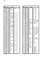
Page 16: ... 100uF 16V C80 UR837470 C EL 47uF 16V C81 UR867100 C EL 10uF 50V C82 UR867100 C EL 10uF 50V C83 FG644100 C CE 0 01uF 50V C84 FG644100 C CE 0 01uF 50V C85 FG644100 C CE 0 01uF 50V C86 UJ749220 C EL 2200uF 25V C87 FG644100 C CE 0 01uF 50V C88 UR867470 C EL 47uF 50V C89 UR867470 C EL 47uF 50V C90 UR867470 C EL 47uF 50V C93 UR867470 C EL 47uF 50V C94 UR867220 C EL 22uF 50V C95 UR867470 C EL 47uF 50V C...

Page 17: ...S PIN 6P C501 UR866100 C EL 1uF 50V C502 UR837470 C EL 47uF 16V C503 VU545000 C EL 47000uF 5 5V C504 VJ599100 C CE TUBLR 0 1uF 50V C505 VF467300 C CE TUBLR 0 01uF 16V C506 VF467300 C CE TUBLR 0 01uF 16V C507 UA655100 C MYLAR 0 1uF 50V C508 UA655100 C MYLAR 0 1uF 50V D501 VD631600 DIODE 1SS133 176 HSS104 D502 VD631600 DIODE 1SS133 176 HSS104 D503 VM975300 DIODE ZENR HZS11B2TD 11V D504 VD631600 DIOD...

Page 18: ...A B C D E 1 2 3 4 5 6 7 TX 396L 202 203 204 205 19 EXPLODED VIEW ...

Page 19: ... VV437300 POWER CORD ASS Y B 51 V4857300 REAR PANEL 53 V4887400 TOP COVER GD 53 VV245400 TOP COVER BL 55 VQ709000 CHASSIS 57 V0049900 LEG D60xH16 GD 57 VQ780300 LEG D60xH16 BL 61 VV244600 SUPPORT PCB PCB 63 VZ037300 SUPPORT 75 VY735100 SPACER 82 V2438700 CORD STOPPER 10P1 121 EP600830 BIND HEAD B TITE SCREW 3x8 FCRM3BL 122 EP600250 BIND HEAD B TITE SCREW 3x8 ZMC2Y 123 VN413300 BIND HEAD BONDING B ...

Page 20: ...o 1 0 Ω HJ35 3100 HF85 3100 1 8 Ω HJ35 3180 2 2 Ω HJ35 3220 HF85 3220 3 3 Ω HJ35 3330 HF85 3330 4 7 Ω HJ35 3470 HF85 3470 5 6 Ω HJ35 3560 HF85 3560 10 Ω HF45 4100 HF45 4100 15 Ω HJ35 4150 HF85 4150 22 Ω HF45 4220 HF45 4220 27 Ω HJ35 4270 HF85 4270 33 Ω HF45 4330 HF45 4330 39 Ω HJ35 4470 HF85 4390 47 Ω HF45 4470 HF45 4470 56 Ω HF45 4560 HF45 4560 68 Ω HF45 4680 HF45 4680 75 Ω HF45 4750 HF45 4750 82...

Reviews: