background image

3.6m x 3.6m (12’ x 12’) WOOD GAZEBO 

with ALUMINUM ROOF

Installation and Operating Instructions – YM12810X

Revised 07-31-2020


12'-1 5/32"

3687.1


12'-1 5/32"

3687.1


HEIGHT:

3.2m (10.5’)

Y40000-810X


IMPORTANT, RETAIN FOR FUTURE REFERENCE: READ CAREFULLY

Yardistry – North America

Toll Free Customer Support: 

1.888.509.4382

info@yardistrystructures.com

www.yardistrystructures.com

Regular Hours:  Mon - Fri, 8:30 am - 5:00 

pm EST (excl. holidays)

(For extended hours see our website)                   

English and French Spoken

(12’ 1-5/32”)

(12’ 1-5/32”)

3.687 m

3.687 m

Summary of Contents for YM12810X

Page 1: ...EIGHT 3 2m 10 5 Y40000 810X IMPORTANT RETAIN FOR FUTURE REFERENCE READ CAREFULLY Yardistry North America Toll Free Customer Support 1 888 509 4382 info yardistrystructures com www yardistrystructures com Regular Hours Mon Fri 8 30 am 5 00 pm EST excl holidays For extended hours see our website English and French Spoken 12 1 5 32 12 1 5 32 3 687 m 3 687 m ...

Page 2: ... avoid injury from possible sharp edges of individual elements before assembly During installation follow all safety warnings provided with your tools and use OSHA approved safety glasses Some structures may require two or more people to install safely Check for underground utilities before digging or driving stakes into the ground During assembly it is important to closely follow the instructions...

Page 3: ...roduct and is a requirement of the warranty This warranty does not cover any inspection costs This Limited Warranty does not cover Labour for replacement of any defective item s Incidental or consequential damages Cosmetic defects which do not affect performance or integrity Vandalism improper use or installation acts of nature including but not limited to wind storms hail floods excessive water e...

Page 4: ... as to cause crushing and splintering of wood Check for sharp edges or protruding screw threads add washers if required WOOD PARTS Applying a water repellent or stain water based on a yearly basis is important maintenance to maintain maximum life and performance of the product Check all wood members for deterioration structural damage and splintering Sand down splinters and replace deteriorated wo...

Page 5: ...s keep parts flat straight and snug when connecting METAL PARTS Roofing material may have sharp edges wear safety gloves Remove all plastic covering on both sides of the metal panels directly before installing each piece Place roofing material on a non abrasive surface before and after assembly as it can bend dent and scratch easily The roofing screws can easily crush the roof panels and roof edge...

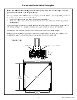
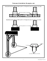
Page 6: ...mounting to concrete footers see below for the correct locations and placement Please double check for possibility of any underground utilities such as gas telephone cable or sprinkler lines Following are some examples of how to mount the structure to wood or concrete surfaces Refer to your local building and city codes ordinances neighbourhood covenants or height restrictions regarding this type ...

Page 7: ... Hardware not included Anchoring Hardware not included Post Mounts Anchoring Hardware not included Post Mounts Concrete Patio min 3 505 m x 3 505 m 11 6 x 11 6 with 15 24 cm 6 clearance on all sides Wood Deck min 3 505 m x 3 505 m 11 6 x 11 6 with 15 24 cm 6 clearance on all sides ...

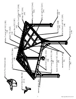
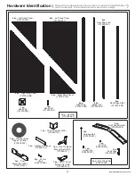
Page 8: ...Rafter Corner Left FSC 333 4x 4X Gusset Left FSC 331 Gusset Right FSC 330 4x 16X 8X Post Mount Plinth FSC 329 Beam End Left FSC 344 4X 4x Rafter Corner Right FSC 334 4X 4X Fascia Left FSC 341 4X Fascia Right FSC 342 4X Strap Short FSC 337 4X Strap FSC 336 4X Rafter Short Right FSC 338 Rafter FSC 340 4X Roof to Beam Bracket X12 Roof To Post Bracket 4x ...

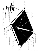
Page 9: ... Nut Carriage Bolt Square Shoulder Peak Cap Peak Post Peak Loop Spring Clip Roof Edge Left 4X Right Short Panel 4X Roof Edge Right 4X Left Short Panel 4X Left Long Panel 4X Right Long Panel 4X Ridge Clip 8X Corner Cap 4X Ridge Cap 4X Weather Seal Ridge Clip 8X ...

Page 10: ...c 346 Beam End Short FSC 31 8 x 82 6 x 2628 1mm Y50229 336 Strap FSC 4pc 336 1 1 4 x 3 1 4 x 10³ 7 16 38 1 x 139 7 x 1790 7mm Y50229 344 Beam End Left FSC 4pc 344 1 1 2 x 5 1 2 x 70 1 2 38 1 x 139 7 x 1790 7mm Y50229 345 Beam End Right FSC 4pc 345 1 1 2 x 5 1 2 x 70 1 2 31 8 x 82 6 x 1866 9mm Y50229 342 Fascia Right FSC 4pc 342 1 1 4 x 3 1 4 x 73 1 2 Y50229 334 25 4 x 88 9 x 2631 5mm Rafter Corner...

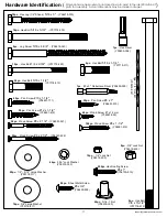
Page 11: ...1 510 40pc Wood Screw 7 x 18 mm Y06091 003 200pc Hex Roofing Screw 8x 1 Y06730 510 24pc Sheet Metal Screw 8 x 3 4 Y06430 503 1pc Hex Driver Y00400 004 Hardware Identification Dimensions are approximate and are shown to assist in the identification of parts for assembly Actual dimensions may be smaller or larger 96pc Wood Screw 8 x 2 1 2 Y06091 522 1pc 2 x 2 Robertson Driver Y00400 005 36pc Pan Scr...

Page 12: ...70800 104 1pc Roof To Beam Bracket Set 12Pk Y70829 151 1pc Post Mount Set 8Pk Y70819 057 2pc Roof Peak Bracket Y00430 068 1pc Roof Set Y70830 084 1pc Roof Peak Set Y70830 068 Dimensions are approximate and are shown to assist in the identification of parts for assembly Actual dimensions may be smaller or larger Hardware Identification 4pc Ridge Cap Y01030 093 4pc Roof Edge Left Y01030 091 8pc Ridg...

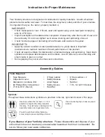
Page 13: ...ties or sprinkler line locations prior to excavating any holes D Before you discard your cartons fill out the form below The carton I D stamp is located on the end of each carton Please retain this information for future reference You will need this information if you contact the Consumer Relations Department Each step indicates which bolts and or screws you will need for assembly as well as any f...

Page 14: ... on each side of the 867 7 x 7 Post and attach with four 8 x 1 1 2 Wood Screws per plinth Rounded edges on top fig 2 1 2 2 and 2 3 C Repeat Steps A and B three more times to make four Post Assemblies 329 Plinth Tight 4 x 867 7 x 7 Post 16 x 329 Plinth 16 x 10 x 1 1 4 Pan Screw 16 x 8 x 2 1 2 Wood Screw 64 x 8 x 1 1 2 Wood Screw 8 x Post Mount Top Bottom 8 x 2 1 2 Wood Screws x 2 per Post Mount fro...

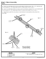
Page 15: ...er 1 4 5 16 large washer and 5 16 t nut per end as shown in fig 3 1 and 3 2 C Repeat Steps A and B three more times to make four Beam Short Assemblies and four Beam End Assemblies 344 Beam End Left 4 x 344 Beam End Left 4 x 345 Beam End Right 8 x 346 Beam End Short 4 x 343 Beam Fig 3 1 24 x 5 16 x 1 1 2 Hex Bolt 5 16 lock washer 1 4 5 16 large washer 5 16 t nut Fig 3 2 1 4 5 16 Large Washer 5 16 x...

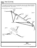
Page 16: ...he ends are flush Match the bolt holes in each 346 Beam End Short with the bolt holes in 344 Beam End Left and 345 Beam End Right Attach with 18 8 x 2 1 2 Wood Screws fig 3 3 and 3 4 E Repeat Step D three more times to make four Beam Assemblies Flush Beam Short Assembly Beam End Assembly 8 x 2 1 2 Wood Screws x 18 per assembly 344 Beam End Left 345 Beam End Right 346 Beam End Short 346 Beam End Sh...

Page 17: ...ck nut per Post The distance from the outside of one Post to the outside of the second Post should be 11 0 fig 4 1 4 2 and 4 3 C Continue until all four Beam Assemblies are attached and the corners are tight together fig 4 1 and 4 2 See fig 4 3 for accurate positioning of Posts Fig 4 2 Hardware 8 x 3 8 x 10 1 2 Hex Bolt 3 8 large washer x 2 3 8 lock nut Note hole orientation on bottom Fig 4 3 9 8 ...

Page 18: ...e Pergola Room on will determine how you anchor it to that surface Please refer to pages 6 and 7 for installation examples Any hardware or extra materials for mounting will have to be purchased in advance Hardware 8 x 5 16 x 4 3 4 Lag Screw 1 4 5 16 large washer 1 4 5 16 Large Washer 5 16 x 4 3 4 Lag Screw 5 16 x 4 3 4 Lag Screw Fig 4 4 Beam Assembly Beam Assembly Post Assembly Step 4 Frame Assemb...

Page 19: ...d 5 3 D At each corner tight to the outside edges of the joining Beam Assemblies attach one Roof to Post Bracket with two 10 x 1 1 4 Pan Screws fig 5 3 and 5 4 Step 5 Attach Gussets and Roof Brackets Fig 5 1 Tight 4 x 330 Gusset Right 4 x 331 Gusset Left Hardware Wood Parts 16 x 1 4 x 3 Hex Lag 1 4 5 16 large washer 16 x 5 16 x 3 3 4 Hex Bolt 5 16 lock washer 1 4 5 16 large washer 5 16 t nut 8 x 1...

Page 20: ... 6 1 and 6 2 B Repeat Step A three more times to make four Fascia Beam Assemblies Step 6 Fascia Beam Assembly Fig 6 1 Fig 6 2 Hardware Wood Parts 4 x 341 Fascia Left 4 x 342 Fascia Right 4 x 5 16 x 1 1 4 Hex Bolt 5 16 lock washer 1 4 5 16 large washer 5 16 t nut 342 Fascia RIght 341 Fascia Left 342 Fascia RIght 341 Fascia Left 1 4 5 16 Large Washer 5 16 T nut 5 16 x 1 1 4 Hex Bolt Tight 5 16 Lock ...

Page 21: ... and 7 4 C Repeat Steps A and B three more times to make four Roof Rafter Assemblies Hardware Wood Parts 8 x 2 1 4 Wood Screws x 6 per Fascia Beam Assembly 340 Rafter Top View Fascia Beam Assembly Step 7 Roof Rafter Assembly Part 1 Fig 7 1 40 x 8 x 2 1 4 Wood Screw 4 x 340 Rafter 4 x 333 Rafter Corner Left 4 x 334 Rafter Corner Right Fig 7 3 Fig 7 4 Note notches facing up Flush Fascia Beam Assembl...

Page 22: ...Corner Left 334 Rafter Corner Right and 340 Rafter so the ends do not overhang the outside edges of the outside boards Do not attach yet fig 7 5 F Place one 338 Rafter Short Right and one 339 Rafter Short Left in the notches of 336 Strap and attach as shown in fig 7 5 with four 8 x 1 1 2 Wood Screws and two 8 x 2 1 4 Wood Screws per board G Attach 336 Strap to 333 Rafter Corner Left 334 Rafter Cor...

Page 23: ... Left and 340 Rafter attach one Roof to Beam Bracket per board with one 8 x 1 Pan Screw in the bottom hole and one 12 x 1 1 2 Pan Screw in the top hole per bracket One Roof Rafter Assembly will not have brackets fig 8 1 and 8 2 Step 8 Attach Roof to Beam Brackets 9 x 8 x 1 Pan Screw 9 x 12 x 1 1 2 Pan Screw 9 x Roof to Beam Bracket Back View 340 Rafter 339 Rafter Short Left 338 Rafter Short Right ...

Page 24: ...y as it can bend dent and scratch easily WARNING DO NOT OVER TIGHTEN ROOFING SCREWS Over tightening screws will cause roofing material to crush The roofing screws can easily crush the Roof Panels and Roof Edges when using a power drill We recommend hand tightening the roofing screws so that they sit snug and tight to the roofing material STOP STOP STOP STOP Overtightened and Crushed Snug and Tight...

Page 25: ...sharp edges Wear gloves BE SURE TO REMOVE ALL PLASTIC COVERING ON BOTH SIDES OF THE ALUMINUM PANELS AND TRIM DIRECTLY BEFORE INSTALLING EACH PIECE One side is clear and the other is blue both must be removed STOP STOP STOP STOP Overtightened and Crushed Snug and Tight Example 1 Example 2 Example 3 ...

Page 26: ... 9 1 and 9 2 C Attach both Left and Right Long Panels to Roof Rafter Assembly with four 8 x 1 Roofing Screws in locations shown in fig 9 1 Be sure not to overtighten screws D Repeat Steps A C for all four Roof Rafter Assemblies Fig 9 1 Fig 9 2 16 x 8 x 1 Roofing Screw Roof Parts 4 x Left Long Panel 4 x Right Long Panel Front View Fascia Beam Assembly 333 Rafter Corner Left 334 Rafter Corner Right ...

Page 27: ... Rafter Corner Right and a slight overhang at the bottom of the Fascia Beam Assembly There should be no overhanging at the corners fig 9 3 and 9 4 G Attach all panels to Roof Rafter Assembly with 29 8 x 1 Roofing Screws in locations shown in fig 9 3 Do not place any screws along the bottom row Be sure not to overtighten screws H Repeat Steps E G for all four Roof Rafter Assemblies 333 Rafter Corne...

Page 28: ...Place one Weather Seal on the inside of each Ridge Clip then place one Ridge Clip on each side of each Roof Rafter Assembly so they cover the panels and attach with five 7 x 3 4 Wood Screws per Ridge Clip fig 10 1 10 3 and 10 4 Weather Seal Ridge Clip Fig 10 2 7x 3 4 Wood Screws x 5 per side Panels Componets 4 x Roof Edge Left 4 x Roof Edge Right 8 x Ridge Clip 8 x Weather Seal Ridge Clip Roof Edg...

Page 29: ...aise it up so the middle Roof to Beam Bracket is lined up with the centre mark fig 11 1 and 11 2 Step 11 Attach Roof Panels to Frame Part 1 Fig 11 1 In front of Post Assembly Beam Assembly Post Assembly 1 499 m Roof Panel Assembly Mark centre location Mark centre location Mark centre location x 3 Beam Assembly Roof to Beam Bracket Fig 11 2 Beam Assembly Line middle bracket to centre mark One assem...

Page 30: ...nnect Roof Panel Assemblies through the Rafter Corners with three 1 4 x 2 3 4 Hex Bolts with two 1 4 5 16 large washers and one 1 4 lock nut To align bolt holes helper in the centre may have to push up the centre of the panels and others make sure corners are aligned Make sure all bolts are tight fig 11 2 and 11 5 Fig 11 2 Flush Fig 11 3 Beam Assembly x 3 Line middle bracket to centre mark Rafter ...

Page 31: ... Panel Assemblies through the Rafter Corners with three 1 4 x 2 3 4 Hex Bolts with two 1 4 5 16 large washers and one 1 4 lock nut To align bolt holes helper on the centre ladder may have to push up in the centre of the panels and others make sure corners are aligned Make sure all bolts are tight fig 11 7 Roof Panel Assembly Fig 11 7 Hardware 3 x 1 4 x 2 3 4 Hex Bolt 1 4 5 16 large washer x 2 1 4 ...

Page 32: ...hen Spring Clip The Spring Clip holds the assembly together fig 12 1 B Insert 1 4 Nut into Peak Loop Be careful nut is loose and will fall out until attached to Peak Cap Assembly fig 12 2 Fig 12 1 Peak Post Componets 1 x Roof Peak Set 1 x Carriage Bolt 1 x Peak Loop 1 x Spring Clip 1 x 1 4 Nut 1 x Peak Cap 1 x Peak Post Step 12 Roof Peak Assembly Fig 12 2 ...

Page 33: ...Carriage Bolt and twist to tighten loosely C Loosely attach both Roof Peak Brackets to the Rafter Corners in the slotted holes with two 10 x 1 1 4 Pan Screws as shown in fig 13 3 Fig 13 1 Roof Peak Bracket Roof Peak Assemlby Components 2 x Roof Peak Brackets Step 13 Attach Roof Peak to Roof Panels x 3 Rafter Corners Rafter Corners Rafter Corners Fig 13 2 Rafter Corner Roof Peak Bracket 10 x 1 1 4 ...

Page 34: ...l fits under the Peak Cap push up on Peak Loop to lift Peak Cap The centre of the other panels may have to be pushed up to fit fourth panel fig 14 1 and 14 2 B Check again that Peak Cap is lined up with Rafter Corners fig 14 3 Roof Panel Assembly Peak Cap Roof Panel Assembly Step 14 Attach Final Roof Panel Part 1 x 3 Rafter Corners Peak Cap Roof Panel Assembly Rafter Corners Fig 14 3 ...

Page 35: ...n bolt holes helper on the centre ladder may have to push up in the centre of the panels and others make sure corners are aligned Tighten bolts when all six have been installed fig 14 4 and 14 5 Rafter Corners should be aligned with Roof to Post Bracket Rafter Corner Hardware 1 4 Lock Nut 1 4 x 2 3 4 Hex Bolt Fig 14 4 Fig 14 5 Roof Panel Assembly Bottom holes first x 3 Step 14 Attach Final Roof Pa...

Page 36: ... per board with one 8 x 1 Pan Screw in the bottom hole and one 12 x 1 1 2 Pan Screw in the top hole per bracket fig 14 6 x 3 Fig 14 6 Parts removed for clarity Roof to Beam Bracket 12 x 1 1 2 Pan Screw Flush Attach to Rafter Short Right Rafter Short Left and Rafter 8 x 1 Pan Screw Hardware 3 x 8 x 1 Pan Screw 3 x 12 x 1 1 2 Pan Screw 3 x Roof to Beam Bracket Step 14 Attach Final Roof Panel Part 3 ...

Page 37: ...embly Ends with two 8 x 2 1 2 Wood Screws per corner A helper may need to lift the centre of the roof to bring the corners tight together fig 15 1 and 15 2 C Align Roof Panel Assemblies to sit centred on Roof to Post Brackets then attach with two 8 x 1 Pan Screws per bracket fig 15 3 8 x 1 Pan Screw Fig 15 1 Fig 15 2 Fascia Beam Assembly Fascia Beam Assembly Fascia Beam Assembly Fascia Beam Assemb...

Page 38: ... the bottom of the assemblies then attach with four 8 x 3 4 Sheet Metal Screws per Corner Cap fig 16 1 and 16 2 Hardware 16 x 8 x 3 4 Sheet Metal Screw Componets 4 x Corner Cap Corner Cap Fascia Assembly Fig 16 1 Fig 16 2 8 x 3 4 Sheet Metal Screw Fascia Assembly Tight x 3 Step 16 Attach Corner and Beam Caps 8 x 3 4 Sheet Metal Screw ...

Page 39: ...Brackets to Beam Assemblies with two 12 x 1 1 2 Pan Screws per bracket fig 17 1 and 17 2 Hardware 24 x 12 x 1 1 2 Pan Screw x 3 Step 17 Secure Roof to Beam Brackets Inside View Beam Assembly Fig 17 1 Roof Panel Assembly Fig 17 2 Roof to Beam Bracket 12 x 1 1 2 Pan Screw Beam Assembly ...

Page 40: ...screws in Roof Peak Brackets then attach to Corner Rafters in the remaining holes with fourteen 10 x 1 1 4 Pan Screws fig 18 1 Hardware 14 x 10 x 1 1 4 Pan Screw Fig 18 1 Roof Peak Bracket Rafter Corner Roof Peak Bracket Rafter Corner Rafter Corner Rafter Corner 10 x 1 1 4 Pan Screw x 14 ...

Page 41: ...oop so Ridge Caps fit under Peak Cap then attach with two 8 x 3 4 Sheet Metal Screws per Ridge Cap fig 19 1 19 2 and 19 3 B Tighten Loop to secure Roof Peak Set Hardware 8 x 8 x 3 4 Sheet Metal Screw Componets 4 x Ridge Cap Ridge Cap Ridge Cap Ridge Cap Ridge Clip 8 x 3 4 Sheet Metal Screw Ridge Cap Fig 19 1 Fig 19 2 Fig 19 3 x 3 Cut End Folded End 35 1 2 Note To help Ridge Caps slide on easier us...

Page 42: ...aced anywhere along the Rafter Corners as needed Pre drill with a 1 8 drill bit before installing fig 20 1 and 20 2 Hardware 2 x 50 mm Hooks Fig 20 1 Fig 20 2 Rafter Corner 50 mm Hook Note We have provided 2 hooks for optional use to hold in place any wires if required These hooks are not designed to hold any heavy products such as lights flower pots etc ...

Page 43: ...ith two 8 x 1 Pan Screws This provides warnings concerning safety and important contact information A tracking number is provided to allow you to get critical information or order replacement parts for this specific model fig 20 3 and 20 4 Hardware 2 x 8 x 1 Pan Screw 1 x Gazebo ID Plaque Fig 20 3 Fig 20 4 8 x 1 Pan Screw Gazebo ID Plaque ...

Page 44: ...esale Spain S L U Polígono Empresarial Los Gavilanes C Agustín de Betancourt 17 28906 Getafe Madrid España NIF B86509460 900 111 155 www costco es Costco Wholesale Korea Ltd 40 Iljik ro Gwangmyeong si Gyeonggi do 14347 Korea 1899 9900 www costco co kr Importado por Importadora Primex S A de C V Blvd Magnocentro No 4 San Fernando La Herradura Huixquilucan Estado de México C P 52765 RFC IPR 930907 S...

Page 45: ...45 support yardistrystructures com NOTES ...

Page 46: ...entaires Mail To Enviar por Correo a Envoyer par courrier à Mail To Enviar por Correo a Envoyer par courrier à Yardistry 375 Sligo Road West PO Box 10 Mount Forest Ontario Canada N0G 2L0 Attention Consumer Relations Atención a Servicio de Atención al Cliente À l attention de Service à la clientèle Yardistry would like to say Thank you for your time and feedback Yardistry quiere Agradecerle por su ...

Reviews: