background image


Maintenance Manual 
Serviceman Handbook

MANUAL No.


NCSIE-SP

02-19

Yaskawa Siemens CNC Series

Summary of Contents for CNC Series

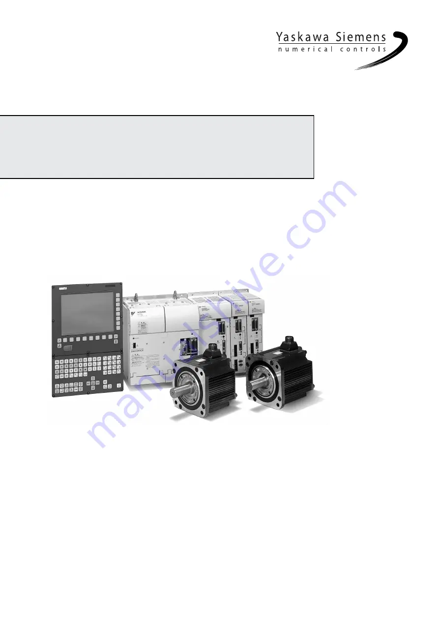
Page 1: ...Maintenance Manual Serviceman Handbook MANUAL No NCSIE SP02 19 Yaskawa Siemens CNC Series...

Page 2: ...should therefore be understood as Siemens Japan K K This manual is intended for both of Yaskawa Siemens 840DI and Yaskawa Siemens 830DI In this manual the functional differences of these two models a...

Page 3: ...Indicates activities that could result in a dangerous condition including major and minor injury or in damage to objects if done wrongly It is noted that those activities as indicated by the symbol m...

Page 4: ...ne or other objects but would result in an alarm Indicates program examples or operation examples Indicates additional information or what you should keep in mind for better efficiency Indicates unfam...

Page 5: ...ations 1 11 Chapter 2 Installing the control panels 2 1 2 1 Designing the panels 2 2 2 1 1 Environmental conditions for installing the control panels and other sy stem components 2 2 2 1 2 Thermal des...

Page 6: ...ss and termination setting 4 19 4 3 2 Setting the rotary switches on the inverters and servo units 4 21 Chapter 5 Assembling and replacing 5 1 5 1 Installing the CNC unit 5 2 5 2 Replacing the servo u...

Page 7: ...NC interface 8 6 8 4 3 Data blocks 8 7 8 4 4 Program components 8 8 Chapter 9 SIMATIC manager and hardware configuration 9 1 9 1 Hardware configuration 9 3 9 2 Defining the hardware 9 4 9 2 1 Creating...

Page 8: ...1 1 1 Startup 11 2 11 1 2 Screen Configuration 11 3 11 1 3 Operation method 11 4 11 1 4 Conditions for the modified parameters to be effective 11 7 11 1 5 Protection level 11 7 11 2 Drive Diagnosis Fu...

Page 9: ...25 12 2 8 Motor current detection signal offset adjustment 12 28 12 2 9 Setting the password setting for write prohibit 12 30 Chapter 13 Drive system overview 1 13 1 13 1 System configuration 13 2 13...

Page 10: ...on 14 59 14 3 3 Positioning 14 63 14 3 4 Emergency stop 14 65 14 3 5 Return to reference point 14 68 14 3 6 Brake control 14 72 14 3 7 Speed feedforward 14 73 14 3 8 Torque Control and Fixed Stop Func...

Page 11: ...ing Spindle motors and Invertors 16 4 16 2 1 Items to be checked daily 16 4 16 2 2 Scheduled maintenance 16 5 16 2 3 Megger test on Spindle motor 16 5 16 2 4 Periodical check 16 6 16 3 Absolute encode...

Page 12: ...anuals Related manuals are listed below which you should read as necessary along with this manual Read all related manuals to grasp the specifications and any usage constraints of the control operatio...

Page 13: ...panels operation panels and other related units and devices Low active signals In this manual low active signals are indicated by the slash symbol followed by their name For example S ON for a low act...

Page 14: ...damage could result After installing the product on the machine remove the eyebolts from the product and attach ordinary bolts of the same size in place of them to close the eyebolt openings Otherwis...

Page 15: ...duct to a strong shock Otherwise damage could result The electric power supplied to the product must be sufficient satisfying its power requirements Otherwise malfunction could result The power requir...

Page 16: ...over and under them to allow them to effectively dissipate their heat Install a servo unit in an enclosure such that the heat sink fins of the unit come out of the enclosure to keep the unit s intern...

Page 17: ...fic operating conditions and required capacity Note that the actual capacity of a cable decreases significantly if the ambient temperature exceeds 30 Determine a correct cable size according to applic...

Page 18: ...rter is equal to the rated voltage of that converter Otherwise injury or a fire could result Do not subject the inverters or converters to a high voltage withstanding test Otherwise their semiconducto...

Page 19: ...e grounding terminal of the corresponding SERVOPACK All wires to be grounded must be directly connected to a single point that is class D or better grounded Otherwise electric shock a fire or malfunct...

Page 20: ...ecessary safety precaution Ensure that the environmental requirements are fully met A fire electric shock or malfunction could result if the product were operated in excessively hot humid dusty corros...

Page 21: ...e factory Do not change the settings unless you know exactly what you are doing Otherwise damage could result When switching on the main power ensure that at least 2 seconds have elapsed after the las...

Page 22: ...rting maintenance work Be aware that capacitors can have a high voltage charge for a while even after the circuit breaker is switched off Only qualified personnel may perform maintenance or service wo...

Page 23: ...ification or specification change to the product or to make it easier to read An updated document No means a new version of this manual If you need additional copies of this manual to replace damaged...

Page 24: ...g Wait 5 minutes for capacitor discharge after disconnecting power supply Risk of electric shock Do not touch the terminals while the product is switched on or for 5 minutes after the product is switc...

Page 25: ...els xxv Warning marking Ground the unit by connecting a grounding wire to this grounding terminal 200V SERVOPACK SGDK 75AEA 200V CN5 A B SW1 RDY CHARGE CN1 CN6 CN2 YASKAWA Position of warning marking...

Page 26: ...Part 1 Hardware...

Page 27: ...stem configuration 1 2 1 1 1 General wiring drawing 1 2 1 1 2 List of system components 1 4 1 2 Meanings of component designations 1 8 1 2 1 SERVOPACK designations 1 8 1 2 2 Servo motor designations 1...

Page 28: ...nted PG PG Pulse 1st motor Spindle motor Converter CIMR MRXN Inverter CIMR MXN Servo unit 1 axis servo SGDK P N CN5B CN7B P N CN1 A1 A2 L1 L2 L3 P N CN5B CN7B POWER U V W E CN4 CN7A CN5A P N P N CN7B...

Page 29: ...encoder Separately mounted encoders are optional for any servo unit or inverter Emergency stop start circuit An emergency stop start circuit must be provided for each converter Thus a system with two...

Page 30: ...uts at 24 VDC source SM321 DI16 120 VAC 6ES7321 1EH01 0AA0 16 inputs at 120 VAC SM321 DI8 120 230 VAC 6ES7321 1FF01 0AA0 8 inputs at 120 230 VAC Digital output module SM322 DO32 24 VDC 0 5A 6ES7322 1B...

Page 31: ...SGDK 15AEA 2 kW servo unit SGDK 20AEA 3 kW servo unit SGDK 30AEA 5 kW servo unit SGDK 50AEA 6 kW servo unit SGDK 60AEA 7 5 kW servo unit SGDK 75AEA 2 axis servo unit 0 5 kW 2 servo units SGDK 0505AEA...

Page 32: ...mm wide units between 150 and 75 mm wide units and between 75 and 75 mm wide units JZSP CNS90 4 1 m long between upper and lower units JZSP CNS90 5 Between 150 and 250 mm wide units and between 75 and...

Page 33: ...e and B means available PROFIBUS DP connector 35 degree connection type connector 6ES7972 0B 40 0XA0 indicates whether a PG port is available A means not available and B means available PROFIBUS DP co...

Page 34: ...voltage Revision symbol Protection type 5 External cooling 2 200 V Maximum output 037 030 022 018 015 011 7P5 5P5 3P7 37kW 30kW 22kW 18kW 15kW 11kW 7 5kW 5 5kW 3 7kW 045 45kW Series identifier Specif...

Page 35: ...le below SGDK A E 75 0 5 0 5kW 0505 0 5kW Number 1 axis unit 2 axis unit Capacity Number Capacity 15 1 5kW 1515 1 5kW 10 1kW 1010 1kW 30 3kW 3030 3kW 20 2kW 2020 2kW 60 6kW 1 5kW 50 5kW 1 5kW 75 7 5kW...

Page 36: ...with 24 VDC brake Servo motor capacity kW Shaft end specification Symbol SGMKS 2 3 6 Straight with no key 1 10 tapered with a parallel key Straight with a key and a tap Specification Design category...

Page 37: ...ethod K Fully closed forced air cooling Winding type A Single winding standard 50 ED output 30 30 kW UA AC spindle motor Shaft end specification N No key Blank With a key standard Mounting method 1 By...

Page 38: ...System Configuration 1 2 3 Spindle motor designations 1 12...

Page 39: ...1 3 Heat dissipation 2 6 2 1 4 Power consumption 2 8 2 2 Protecting against electric noise 2 9 2 2 1 Separation of cables 2 9 2 2 2 Noise proof devices 2 10 2 2 3 Grounding 2 12 2 2 4 Cable shield cla...

Page 40: ...r supply module PS module 0 60 Power supply backup module UPS module Power supply backup battery UPS battery 5 40 Machine control panel I O PP module 0 55 I O power supply module PS307 0 60 horizontal...

Page 41: ...cally enclose a CNC or other unit and be so designed as to keep the internal average temperature rise 10 or less Internal average temperature rise The internal average temperature rise for a sheet met...

Page 42: ...d see the table below Table 2 2 Heat exchanger Note Capacity means the amount of heat that a heat exchanger can remove on the ground that the temperature rise must be kept 10 or less Maximum internal...

Page 43: ...uppermost location so as to force the internal air down The external fan must be mounted at a lowermost location so as to force the external air up Fig 2 1 shows an example installation of a heat exc...

Page 44: ...O power supply module PS307 24 VDC 2A output 10 PS307 24 VDC 5A output 18 PS307 24 VDC 10A output 30 Interface module ET200M 4 5 Digital input module SM321 DI32 24 VDC 6 5 SM321 DI16 24 VDC 3 5 SM321...

Page 45: ...Converter CIMR MRXN23P75A 2 5 Inverter CIMR MXN20375A 2 5 CIMR MXN20305A 687 213 474 CIMR MXN20225A CIMR MXN20185A CIMR MXN20155A CIMR MXN20115A CIMR MXN27P55A CIMR MXN25P55A CIMR MXN23P75A 1 axis se...

Page 46: ...UPS BATTERY CNC unit PCU50 Operation panel NC keyboard OP010F Machine control panel OP032S 6W 24 VDC None Machine control panel I O PP module 11W 24 VDC None I O power supply module PS307 2A 10W 200...

Page 47: ...to solenoids contactors and relays DC power 2 24 VDC power supply lines to CNC I O and power supply modules These cables must not be bundled with AC power cables 1 or must be provided with an electro...

Page 48: ...ote A surge absorber must be installed as close to a coil as possible For induction motors Note A surge absorber must be installed as close to a motor as possible Construction of a surge absorber The...

Page 49: ...de DC powered contactors and relays with a diode Note A diode must be installed as close to a coil as possible The recommended voltage and current ratings of a diode are twice the voltage and current...

Page 50: ...otor must be wired to the grounding terminal of the corresponding SERVOPACK All wires to be grounded must be directly connected to a single point whose grounding resistance 100 or less Otherwise elect...

Page 51: ...the system The recommended cable clamping method is that stripping off a length of the insulation of a cable to expose its shielding braid placing a cable clamp over the shielding braid and fixing the...

Page 52: ...oling fan at the top on the rear side Do not place any obstacle that could block the air flow Otherwise damage could result Provide a 100 mm or more space over and a 160 mm or more space under the CNC...

Page 53: ...nk fins are exposed to the out side cooling air to reduce the internal temperature rise This way the panel can be air tight and the size of the heat sink can be designed smaller see the figure below T...

Page 54: ...0 55 inside Apply sealing agent to the mounting screw areas of the SERVOPACK to prevent oil from entering inside The SERVOPACK has a built in fan as shown in Fig 2 6 To prevent the SERVOPACK from ove...

Page 55: ...tallation space for the I O modules The I O modules must be installed as illustrated below Machine control panel I O PP72 48 There must be a 120 mm or more space to the left of the machine control pan...

Page 56: ...h energy disturbance such as switching or lightning surge Normally the power line should be provided with surge absorbers as shown below Normal type surge absorber between phases Common type surge abs...

Page 57: ...witching surge the wiring and devices could burn To prevent this 5 A fuses or other circuit protectors must be provided in the pro tected line Application Designation Make Normal type surge absorber b...

Page 58: ...Installing the control panels 2 3 5 Installing lightning surge absorbers 2 20...

Page 59: ...3 1 Chapter 3 Installing the motors This chapter presents the precautions to be observed when installing the YS 840DI motors 3 1 Servo motors 3 2 3 2 Spindle motors 3 3...

Page 60: ...be used indoor The environmental requirements for the motors are these Indoor and free of corrosive or flammable gas Well ventilated and free of excessive dust dirt or moisture Ambient temperature 0...

Page 61: ...e spindle motor runs at the rated load The bed foundation or mount on which the spindle motor is installed must be rigid enough Otherwise the bed could vibrate due to the weight of the motor and the d...

Page 62: ...Installing the motors 3 4...

Page 63: ...6 4 1 3 I O module 4 6 4 1 4 Converter 4 9 4 1 5 Inverter 4 10 4 1 6 Servo unit 4 11 4 2 Power on off signals 4 14 4 2 1 Wiring for servo power on and other signals 4 14 4 2 2 UPS module timer setting...

Page 64: ...operation panel OP010F The YS 840DI system uses a combination of the CNC unit PCU50 and the operation panel OP010F The surfaces of the combined units are defined as follows Operation panel OP010F Rear...

Page 65: ...ot Do not touch the reset button unless this is what you exactly want 24 VDC input PS 2 mouse PS 2 Mouse PS 2 Keyborad Battery module X121 Handle PG PROFIBUS DP X101 MPI X111 COM1 LPT1 COM2 VGA USB MP...

Page 66: ...1 1 CNC unit 4 4 Remove the mounting rail if you want to combine the CNC unit with the OP010F operation panel Right side surface Grounding terminal Connector for an external 3 5 inch floppy disk drive...

Page 67: ...switches 4 5 The left side surface is not shown because there is no connector on it Rear surface Hard disk drive unit Connector for an external 3 5 inch floppy disk drive Bottom surface with connecto...

Page 68: ...3 4 5 DC USV Modul 10 n c Bat o k Alarm X2 1 2 2 2 3 2 4 2 5 2 6 2 7 2 8 2 9 In L M Out L M Bat Bat X1 1 X1 2 X1 3 X1 4 X1 5 X1 6 t 24V 24V Timer setting 24 V power supply input 24 V power supply out...

Page 69: ...switch System voltage and grounding terminal 24 VDC output terminal Cable clamp With the panel closed With the panel open Panel Slot Version Catalog number Status error indicator PROFIBUS DP interface...

Page 70: ...4 8 Digital I O module SM321 D132 24 VDC Dummy module DM370 0 1 2 3 4 5 6 7 0 1 2 3 4 5 6 7 0 1 2 3 4 5 6 7 0 1 2 3 4 5 6 7 Channel number Status LED green Byte 2 Byte 0 Byte 3 Byte 1 NA A Address sw...

Page 71: ...1 I O connector DC power terminal block 8P M6 CN7A Control power connector CN7B Control power connector CN5A I O bus connector CN5B I O bus connector Indicator red CN8 Battery input CN9 PROFIBUS SW1 P...

Page 72: ...l block 4P M6 CN7A Control power connector CN7B Control power connector CN5B I O bus connector CN5A I O bus connector SW1 Rotary switch RDY Indicator green CN4 Pulse PG input CN1 I O connector CN6 Ana...

Page 73: ...l block 4P M6 screw Control power connector CN7 I O bus connector Rotary switch SW1 Indicator RDY green I O connector CN1 Analog monitor connector CN6 PG input connector CN2 Motor output terminal bloc...

Page 74: ...al block 2P M6 screw I O bus connector CN5 Rotary switch SW1 Indicator RDY green Indicator CHARGE red I O connector CN1 Analog monitor connector CN6 PG input connector CN2 Motor output connector CN8 G...

Page 75: ...rminal block 2P M6 screw Control power connector CN7 I O bus connector CN5 Rotary switch SW1 Indicator RDY RDY2 green Indicator CHARGE red I O connector CN1 Analog monitor connector CN16 CN26 PG input...

Page 76: ...power on and brake release output signals must be done as follows Wiring between units Servo power on output signal SVMX Brake release output signal BKX Converter unit CIMR MRXN CN1 10220 52A2JL UL20...

Page 77: ...otor fan Z1 Z2 Z3 Reactor U V W X Y Z CR To servo motor brake PB X Brake power supply 1 SVM 1 2 3 4 5 6 ESP X Brake power supply 2 BKX 2 1 2 3 4 5 6 ESP X 1 2 1 3 L N E V V 4 5 JUMPER 120VAC ONLY Emer...

Page 78: ...ttery module insert a 15 A fuse in its fuse holder Otherwise an alarm would result When inserting a fuse a spark may occur if the battery is in the charged state Don t worry about the spark since it s...

Page 79: ...ven after a blackout occurs to earn time necessary for memory data to be transferred to a hard disk The relationship between timer setting and covered period is shown below The covered period should b...

Page 80: ...eady Alarm reset manually from machine control panel PBX self held ON SVM servo power ON BKX1 BKX2 ESPX forced braking ON OFF SW manual NC contact UPS BAT ON NC contact UPS start signal Brake power su...

Page 81: ...d termination setting Example wiring PCU50 DP address switch 3 IM module I O module Termination OFF IM module I O module Termination OFF Machine control panel I O S1 8 X2 Machine control panel I O S1...

Page 82: ...ace module to a value between 3 and 32 such that each unit has a unique value Converter Set the DIP switch to a value between 3 and 32 such that each unit has a unique value Termination setting Set th...

Page 83: ...e value Thus if a 2 axis servo unit has its rotary switch set to 2 the val ues 2 and 3 are actually used by those two axes and the next unit must have its rotary switch set to 4 A 2 axis servo unit sh...

Page 84: ...Connection method 4 3 2 Setting the rotary switches on the inverters and servo units 4 22...

Page 85: ...cing the 0 5 3 0 and 5 0 kW servo unit fans 5 8 5 2 2 Procedure for replacing the 6 0 and 7 5 kW servo unit fans 5 9 5 3 Installing the servo unit optional board 5 10 5 3 1 Procedure for installing th...

Page 86: ...The CNC unit of the YS 840DI system is normally delivered with the operation panel attached to it Make any necessary adjustment to the CNC unit or the operation panel sepa rately and then assemble th...

Page 87: ...om the CNC unit by unscrewing 4 M4 screws and 4 M3 screws A Torx wrench or Torx screwdriver is required for this work 3 Connect 2 flat cables from the operation panel to the CNC unit Ensure that the c...

Page 88: ...four M4 screws and four M3 screws Use a Phillips screwdriver 5 Turn the hard disk operation switch on the back of the CNC unit to the operating posi tion until it clicks 6 Unscrew two M3 screws from...

Page 89: ...1 Installing the CNC unit 5 5 7 Unscrew one M3 screw from the slot cover and then remove the slot cover 8 Open the MCI Extension Board selector lever S1 Selector lever S1 Release this part Open Close...

Page 90: ...oard into the optional board slot as far as it will go 10 Connect the MCI Extension Board connector to the corresponding connector on the board above it using the supplied cable Ensure that the connec...

Page 91: ...ix the MCI Extension Board in position with the slot cover screw 12 Reinstall the top cover and secure it with the screws A Torx wrench or a Torx screwdriver is required for this operation This step c...

Page 92: ...he servo unit fans as follows 1 Open the PN cover 2 Unscrew the screw that holds the fan unit The screw will remain loosely attached to the panel cover 3 Remove the fan unit 4 Disengage the connector...

Page 93: ...servo unit fans as follows 1 Unscrew the screw that holds the fan cover The screw will remain loosely attached to the fan cover 2 Remove the fan 3 Disengage the fan connector 4 Replace the fan with a...

Page 94: ...talling the board for the 0 5 3 0 and 5 0 kW servo units Install the optional board as follows 1 Unscrew the screws that hold the optional board cover and remove the cover 2 Cut the blind plates off 3...

Page 95: ...onal board as follows 1 Unscrew the screws that hold the optional board cover and remove the cover 2 Remove the blind plate NP 3 Install the NPs on the optional board cover 4 Install the optional boar...

Page 96: ...Part 2 Software...

Page 97: ...6 1 Chapter 6 Software configuration 6 1 System software components 6 2 6 2 Data types 6 3 6 3 Service screen directories 6 4...

Page 98: ...as the software is revised Table 6 1 System software components Hardware Software component Version System number HMI Windows NT 4 0 SP6 Service Pack Example 00 02 00 YS 840DI Start up V01 00 08 MMC 1...

Page 99: ...Part Program System program Sub Program Mostly machining subprograms with the SPF extension Work pieces User data for machining main pro grams NC data Option data Stored in the resident directory Mach...

Page 100: ...IR DIR Temporary directory WORK WORK PIECES DIR Storing various machining programs machine specific data files WKS wks dir Tool management DIR Storing configuration and tool list data WZV wzv dir Diag...

Page 101: ...lection by the MMC extension Directory names in the folder dh of the F drive YS 840DI as displayed by the NT s Explorer Manufacturer cycle DIR Storing custom cycles created by the user CMA Cma dir Use...

Page 102: ...Software configuration 6 6...

Page 103: ...7 1 Chapter 7 Backup 7 1 How to archive 7 2 7 2 Network settings 7 7 7 2 1 YS 840DI settings 7 7 7 2 2 PC settings 7 14...

Page 104: ...or archive programs or data individually follow the procedure described below Assuming to archive a machining program 1 Click on Service which is at the lower left corner of the screen 2 Click on Data...

Page 105: ...7 1 How to archive 7 3 3 Select the Workpieces folder 4 Click on Archive File which is one of the right side keys...

Page 106: ...Backup 7 4 5 The target screen will appear Enter an archive name WKS0214 in this example in the archive name field 6 Click on Start which is one of the right side keys...

Page 107: ...7 1 How to archive 7 5 7 The part program archive data will be written in the hard disk as shown below 8 After a while an archive file named WKS0214 will be created in the archive folder...

Page 108: ...Backup 7 6 9 All archive data is stored in F dh ARC dir Use the Explorer to copy the created archive data to a PC as necessary 10 To restore the archive data click on Data Input and then Archive File...

Page 109: ...that data as may be stored in the hard disk can be trans ferred from the YS 840DI system to a PC as described below 7 2 1 YS 840DI settings The procedure for the network settings on the YS 840DI is as...

Page 110: ...Backup 7 2 1 YS 840DI settings 7 8 2 Double click on Network in the control panel window 3 With the following window displayed click on Change...

Page 111: ...7 2 Network settings 7 9 4 Enter in the Workgroup field the name YS 840DI3 in this example of the workgroup of the destination PC Click on OK 5 With the following message displayed click on OK...

Page 112: ...Backup 7 2 1 YS 840DI settings 7 10 6 Click on the Protocols tag 7 Select TCP IP Protocol from Network Protocols and click on Properties...

Page 113: ...7 2 Network settings 7 11 8 Click on the radio button to the left of Specify an IP address...

Page 114: ...on OK The IP address 1 1 1 1 and the subnet mask 255 255 255 0 as used in this example are just examples In practice these values must be changed to correct ones such that they are compatible with tho...

Page 115: ...he Network window click on OK 11 With the following message displayed click on YES 12 After a while the YS 840DI system restarts and the Windows NT gets ready for com munication with the target PC If...

Page 116: ...e procedure for the network settings on a target PC running Windows 98 is as follows 1 Switch on the target PC and let it run Window 98 Select Start Settings Control Panel to display Control Panel 2 I...

Page 117: ...rk settings 7 15 3 In the Network window select Windows Logon as a preferred network to log on 4 Select Client for Microsoft Networks from the following network components are installed and click on P...

Page 118: ...16 5 Uncheck the square to the left of the line log on to Windows NT domain Click on OK 6 Select TCP IP the actual display depends the LAN card used from the following net work components are install...

Page 119: ...5 255 0 in the Subnet Mask field Click on OK The IP address 1 1 1 2 and the subnet mask 255 255 255 0 as used in this example are just examples In practice these values must be changed to correct ones...

Page 120: ...an example The workgroup name entered here can be any name provided that the same name is also specified on the YS 840DI side The computer name can be any name provided that it is in alphanumerics su...

Page 121: ...7 2 Network settings 7 19...

Page 122: ...Part 3 PLC...

Page 123: ...nced features programs are not only easy to understand but far more powerful than the conventional ladder logic The PLC for the YS 840DI sys tem is the S7 300 allowing the use of LAD FBD and STL in la...

Page 124: ...programs in LAD or FBD can be rewritten in STL but not all programs in STL can be rewritten in LAD or FBD FBD STL STL All programs convertible Most programs convertible M o s t p r o g r a m s n o t c...

Page 125: ...xed LAD and STL networks or mixed FBD and STL networks LAD and FBD networks however cannot be mixed in a block While most instructions can be written in any of LAD FBD and STL the LOOP variable addres...

Page 126: ...BX1 1 T Timer T24 C Counter C15 P Peripheral e g analog direct I O access PIW128 PQW128 Local stack L1 2 LW2 Byte address Bit address Address symbol I 0 0 I 0 1 I 0 2 I 0 3 I 0 4 I 0 5 I 0 6 I 0 7 I 1...

Page 127: ...y a digit between 0 and 7 the 8 bits make up a byte Byte address The byte address part of a bit address is the numerical part after the address symbol and before the period It is represented by an int...

Page 128: ...d through the interface NC kernel NCK information Mode group information Channel information Feed spindle information 8 4 2 Signals through the PLC NC interface The flow of signals through the interfa...

Page 129: ...urrent mode DB19 Signals sent through the PLC MMC interface as shown below Control signals MCS or WCS current position display and key disable Machine operation Input from the machine control panel PL...

Page 130: ...s For details on OB FC and FB see the System Software for S7 300 S7 400 System and Standard Functions OB100 restart process OB1 cycle process at each scanning User program OB40 interrupt process FC al...

Page 131: ...edit a PLC ladder program during machining some restrictions apply to sav ing 9 1 Hardware configuration 9 3 9 2 Defining the hardware 9 4 9 2 1 Creating a new project 9 4 9 2 2 Adding a station 9 5...

Page 132: ...IC manager and hardware configuration 9 2 9 3 Uploading hardware configuration 9 20 9 3 1 Uploading hardware configuration 1 9 20 9 3 2 Uploading hardware configuration 2 9 21 9 3 3 List of addresses...

Page 133: ...ss and other CPU properties Addressing of the I O modules Setting of the range and addresses of the analog inputs The hardware configuration screen consists of the following three windows Station edit...

Page 134: ...ting projects as listed below You can select any directory under which the project will be by using the browse but ton The default directory is SIEMENS STEP7 S7_Proj This is the recommended directory...

Page 135: ...me can be changed freely Now you are ready for hardware configuration When adding a station if you select Insert New Object S7 program a program container is created under the project The container co...

Page 136: ...ware configuration is displayed If not a blank window results see the figure above 3 Click on the catalog icon of the hardware configuration screen s tool bar A hardware catalog is displayed listing t...

Page 137: ...When you open the hardware configuration of a newly created station a blank frame will show up in the hardware configuration window You must first add a rack on which you are going to put modules 1 E...

Page 138: ...CP module be inserted in the main rack as it cannot always be inserted in a supplementary rack 9 2 6 Adding the power supply module Insert the power supply module first in slot 1 When adding the power...

Page 139: ...rted in a slot a property screen may automatically appear for that module The content of a property screen depends on the type of a module The properties of each module are described later in this cha...

Page 140: ...rts the following CPU module families A product designation is in the following format Each CPU module has its designation displayed in the CPU module list in the hardware catalog Note that a CPU modu...

Page 141: ...button to display the network properties screen To check or modify the properties of an existing network click on the Proper ties button 3 Select a PROFIBUS type 4 Select a transmission rate accordin...

Page 142: ...ending from the CPU slot in the hardware configuration window If the rack is hiding the line move the rack aside DP slaves can be added so as to connect to the line If a CPU with a DP port is used but...

Page 143: ...ies screen appears 3 Specify a unique number between 1 and 125 as the node address 4 Click on OK A node is displayed for the selected DP slave in the hardware configura tion screen Double clicking on...

Page 144: ...node 3 For the ET200M and other nodes that require module configuration select an I O mod ule from the hardware catalog and move it into the rack details window as is the case for the CPU rack With th...

Page 145: ...lick on a slot containing a module to display the properties screen for that module Specify or confirm the start address of the module on the address sheet no start address can be specified for some C...

Page 146: ...the racks as shown below For the S7 300 racks this operation is not necessary because when the interface module IM is installed in each of the racks the interfaces are automatically connected together...

Page 147: ...initiates the compilation process A compiled hardware configuration is saved in the system data block in the block container of the SIMATIC manager Save The hardware configuration is saved but not com...

Page 148: ...licking on OK The MPI address to be specified must be that to which a PLC is actually connected and the hardware configuration can be downloaded If only one PLC is connected simply click on OK 5 The p...

Page 149: ...nfiguration can be downloaded If the downloading is started with the mode switch set to the RUN P position the following con firmation message will be displayed The CPU run state is to be switched fro...

Page 150: ...ration information to a project 1 Open the SIMATIC manager screen and create a new project or open an existing project and click on a project name 2 Open the PLC menu and select Upload Station Upload...

Page 151: ...9 3 2 Uploading hardware configuration 2 The other method by which you can upload the hardware configuration information of a CPU to a project is this 1 Click on the Upload icon of the hardware confi...

Page 152: ...ained Slot Specify the number 2 for the S7 300 of the slot in which the source CPU is inserted Address Specify the node address normally 2 of the source CPU 4 Click on the OK button and the hardware c...

Page 153: ...own The name of CP is also shown if the CP is configured as a DP master Filter Input Input addresses are to be listed Output Output addresses are to be listed Address gap Address gaps are to be listed...

Page 154: ...Part 4 Setting up and maintenance...

Page 155: ...10 1 Chapter 10 Overview of System 10 1 Screen operation 10 2 10 1 1 Basis concept 10 2 10 1 2 Basic operation 10 3 10 2 MD components 10 5...

Page 156: ...kawa Siemens 840DI Maintenance Manual NCSIE SP02 10 10 1 1 Basic concept YS 840DI employs the screen system called ShopMill as the operation control basic screen from which you can call the screens re...

Page 157: ...lation Program modificatio n STEP7 HS5 HS6 HS7 HS8 Setting data User data 1 If the exclusive customer screen is added the alignment between HS1 and HS8 may be changed T S M Zero offset origin setting...

Page 158: ...rent screen belongs However the content of the screen remains unchanged MACHINE M key This allows you to change the screen level from the lower to the top layer of each func tion For example on the lo...

Page 159: ...page s per axis SP X axis Y axis Z axis B axis Spindle inverter MXN Feed X axis SGDK Feed Y axis Feed Z B axis 1 axis drive 1 axis drive 2 axis drive 1 axis drive Drive parameter Spindle MD 6000 to 89...

Page 160: ...Overview of System 10 1 2 Basic operation 10 6...

Page 161: ...effective 11 7 11 1 5 Protection level 11 7 11 2 Drive Diagnosis Function 11 8 11 2 1 Drive diagnosis screen initiation 11 8 11 2 2 Drive diagnosis screen configuration 11 8 11 3 Mapping ACC file 11...

Page 162: ...eter screen which is housed in YS 840DI standard HMI applica tion 11 1 1 Startup Startup To display the drive parameter screen use the following procedure 1 Select the MENU SELECT key to go to the Top...

Page 163: ...F10 F11 F12 F13 F14 F15 F16 Parameter number Name of parameter Selection display Parameter setting value Name of axis Drive number Conditions of validity Unit Description of selected parameter Drive d...

Page 164: ...ey Drive key Direct selection key Search key and Continuous search key are not available Input of setting value The input method of setting values are categorized into 3 types decimal number hexadeci...

Page 165: ...e final page Press the Direct selection F11 key to display the dialog box for direct switching see the figure below Press the INSERT key to display the list of drives you can switch over When selectin...

Page 166: ...arching With every press on the Con tinue search F15 key searching is taken place from the current cursor position down to the bottom When having reached the bottom line searching is continued from th...

Page 167: ...he modified parameter you must execute the NCK Reset Alternatively cut off and then turn on the drive power supply im The modified parameter becomes effective just after modification You need not cut...

Page 168: ...ation To start up the drive diagnosis screen activate the drive parameter screen and then press the Drive Diagnosis F2 key see the section 11 1 2 Screen configuration 11 2 2 Drive diagnosis screen con...

Page 169: ...e you can diagnose the state of drive The indication is shown OK NG or No drive Each sign is explained below Read Write Drive state OK The state of drive can Read Write the parameter NG The state of d...

Page 170: ...meter screen is created on the basis of the informa tion of ACC file 11 3 2 Mapping ACC file To read write the drive parameter you must beforehand register the parameter by mapping Just after initiati...

Page 171: ...Drive Direct selection Search Continue search and Refresh can not be enabled When the normal communication with all the drives is recovered the screen automatically comes back to the normal display T...

Page 172: ...ile Mapping failed Mapping of ACC file has failed No drive is available The drive is not connected Or the drive is not powered on Please wait until all drives are available This indication is displaye...

Page 173: ...tching the basic mode 12 4 12 1 5 Axis selection mode 12 5 12 1 6 Status display mode 12 5 12 1 7 User Constant Setting Mode 12 8 12 1 8 Operation on the monitor mode 12 12 12 2 Application 12 17 12 2...

Page 174: ...l Operator is a hand held operator JUSP OP02A 2 which can be attached to the connector CN3 of converter The following figure shows where to attach the digital operator to the converter The digital ope...

Page 175: ...the setting and setting value of each user constant press this key To switch over the axis selection mode and the status display mode press this key Value modi fication JOG key UP key To increase the...

Page 176: ...s basic mode includes the status display mode auxiliary function execute mode constant setting mode and monitor mode These modes can be switched over in the following order by pressing the key Power s...

Page 177: ...ayed Now the second axis has selected To return to the axis selection mode press the DATA ENTER key on the status display mode The first axis of the 1 axis drive and 2 axis drive is the rotary switch...

Page 178: ...1 TGON Lights when the motor speed is higher than the specified value Goes out when the speed is lower than the specified value Specified value Set with Pn502 Standard value is 20 min 1 Speed referenc...

Page 179: ...N Lights when the motor speed is higher than the specified value Goes out when the speed is lower than the specified value Specified value Set with Pn502 Standard value is 20 min 1 Reference pulse is...

Page 180: ...he content of the user constant Pn507 from 100 to 85 1 On the axis selection mode select the axis you want to operate 2 Press the DSPL SET key and select the constant setting mode 3 Select the user co...

Page 181: ...ame Preset value Remarks Constant for function selection Pn000 Function selection basic switch 0070 Pn001 Function selection application switch 1 0000 Pn002 Function selection application switch 2 000...

Page 182: ...lection user constant setting value is defined as followings The example of display shows the user constant display according to this digit definition of the setting value Setting value Indication of...

Page 183: ...DATA ENTER key to display the current data of the user constant that you just selected Step 3 5 Press the LEFT or RIGHT key to select the digit number you want to set 6 Press the UP or DOWN key to sel...

Page 184: ...monitor mode This is the procedure to view the monitor number Un000 data 1500 when the servo motor is running at the speed of 1500 min 1 1 On the monitor mode select the axis you want to operate 2 Pre...

Page 185: ...e 2 deg Angle from the origin Electrical degree Un005 Input signal monitor 1 Un006 Output signal monitor 1 Un007 Position command speed min 1 3 Un008 Value of deviation counter Com mand unit Position...

Page 186: ...ing segment LED of the seven segments flashes When the input signal is ON L level the lower half of the segment flashes and when the input signal is OFF H level the upper half of the segment flashes W...

Page 187: ...r half of the segment flashes and when the output signal is OFF H level the upper half of the segment flashes When the ALM1 signal is enabled in case of L an alarm is output Display LED number Name of...

Page 188: ...selection mode select the axis you want to operate 2 Press the DSPL SET key to select the monitor mode 3 Press the UP or DOWN key to select one from Un00C Un00D and Un00E 4 Press the DATA ENTER key t...

Page 189: ...3 Origin searching mode Fn004 reserved constant Fn005 Initiation of user constant setting value Fn006 Clear of alarm trace back data Fn007 Inertia ratio from the result of on line auto tuning action W...

Page 190: ...the DATA ENTER key to view the alarm trace back data 4 Press the UP or DOWN key to scroll the alarm occurence number The alarm history information is displayed The larger the number on the left side d...

Page 191: ...he axis you want to operate 2 Press the DSPL SET key and select the auxiliary function execution mode 3 Select the user constant Fn006 Press the LEFT or RIGHT key to select the setting digit Press the...

Page 192: ...nd select the auxiliary function execution mode 3 Select the user constant Fn011 Press the LEFT or RIGHT key to select the setting digit Press the UP or DOWN key until the value you want to set is dis...

Page 193: ...unction mode You can also return to the auxiliary function mode by pressing the DATA ENTER key after viewing the indication of Step 4 to Step 6 This completes checking the motor type Encoder resolutio...

Page 194: ...following procedure 1 On the axis selection mode select the axis you want to operate 2 Set Fn012 3 Press the DATA ENTER key to view the SERVOPACK software version 4 Press the DSPL SET key to view the...

Page 195: ...T key to select the setting digit Press UP or DOWN key until the value you want is displayed 4 Press the DATA ENTER key and the screen displays as below 5 Press the SVON key The indication will displa...

Page 196: ...use the following procedure 1 On the axis selection mode select the axis you want to operate 2 Press the DSPL SET key and select the auxiliary function execution mode 3 Select the user constant Fn005...

Page 197: ...on see the section 16 4 Analog Monitor The analog monitor output manual zero adjustment function is used for compensating the output voltage deviation which is caused by drift or the zero point deviat...

Page 198: ...o set is displayed 4 Press the DATA ENTER key The indication will display like below 5 Press the DSPL SET key to switch over the 2 channel monitor output 6 Press the LEFT or RIGHT key to view the anal...

Page 199: ...R key The indication will display like below 5 Press the DSPL SET key to switch over the 2 channel monitor output 6 Press the LEFT or RIGHT key to view the analog monitor gain factor Press the LEFT or...

Page 200: ...When you determine the torque ripple is obviously large in comparison to other SERVOPACK you may execute the automatic adjustment for offset Motor current detection signal offset automatic adjustment...

Page 201: ...ou have to adjust alter nately these phase current offsets several times 1 On the axis selection mode select the axis you want to operate 2 Press the DSPL SET key to select the auxiliary function exec...

Page 202: ...form being rewritten care lessly When setting the password the user constant which is prohibited to write is a part of the constants beginning with Pn or Fn The setting value for passwords are follow...

Page 203: ...e display like following appears and the password is written 6 Press the DATA ENTER key to return to the auxiliary function execution mode dis play This completes the password setting This password se...

Page 204: ...How to use Digital Operation 12 2 9 Setting the password setting for write prohibit 12 32...

Page 205: ...drive refer to the other chapters in this manual for each drive 13 1 System configuration 13 2 13 2 Specification of machine data and parameters 13 3 13 2 1 Structures of machine data and parameters...

Page 206: ...output and latch signal input are input output to Drive system Digital operator connected to a Converter can be used for both a Servo drive and a Spindle drive in common Hardware timer Converter Drive...

Page 207: ...ation MD numbers Display screen Application Remark MD0 2999 Drive parameters Parameters common to Servo drives and spindle drives Data such as Load and Alarm are included Read only No data can be set...

Page 208: ...CNC power is turned on off or NCK Reset is entered cf Parameter becomes active when Set MD Active is entered re Parameter becomes active when CNC panel reset key is pressed im Parameter becomes active...

Page 209: ...xadecimal digits of a param eter Each parameter digit is to be set to a value from 0 to 15 0 FH in hexadecimal notation The digits are numbered from 0 to 3 If it is specified to set parameters in digi...

Page 210: ...yed or entered with fractional portion removed off so that they can be set also from the Digital Operator in the same way In this case the unit displayed together indicates whether or not the data has...

Page 211: ...14 5 14 1 2 NCK processing capability 14 6 14 1 3 Servo control method and fundamental operation 14 6 14 1 4 Axis configuration 14 8 14 1 5 Motor encoder 14 14 14 1 6 External encoder 14 20 14 1 7 Max...

Page 212: ...12 Spindle sequence I O signals 14 85 14 3 13 Spindle orientation 14 87 14 3 14 Spindle winding changing 14 90 14 3 15 Spindle gear changing and Spindle integrated with C axis control 14 92 14 3 16 R...

Page 213: ...4 Quadrant error compensation 14 2 5 Torque reference notch filter 14 2 6 Speed feedback compensation 14 2 7 Predictive control 14 2 8 Model following control 14 2 9 Stop vibration suppression 14 2 1...

Page 214: ...xis and Spindle Item Function Feed axis Spindle Related section Motion control Rigid tapping 14 3 16 Thread cutting 14 3 17 Spindle synchronous control 14 3 18 Skip 14 3 19 High speed and high precisi...

Page 215: ...et Machining center 0 002 sec 2 ms Turning 0 004 sec 4 ms The DP cycle is set through a hardware configuration using a PLC set up tool STEP7 Refer to STEP7 instruction for more information You can che...

Page 216: ...ntrol method and fundamental operation CNC setting The servo control method of YS 840DI system is called DSC Direct Servo Control In this method CNC and drives perform position control to attain high...

Page 217: ...et by MD35020 becomes active Setting value 0 When power is turned on 1 When power is turned on and NC starts 2 When power is turned on and reset M2 and M30 Standard setting value 0 MD35040 SPIND_ACTIV...

Page 218: ...of the Converter and axis numbers under the Converter can be set up 2 Perform a hardware configuration using PLC set up tool STEP 7 so that all the hard ware such as drives and I O modules can be phy...

Page 219: ...uccession to each of the rotary switches The numbers assigned must be sequential otherwise you need to take care in perform ing a hardware configuration In the case of a 2 axis combined Servo drive nu...

Page 220: ...7 axes can be connected to one Converter The following settings are to be made to the STEP7 for the GSD file of drive As mentioned above you can connect up to 7 axes to one Converter and you can sele...

Page 221: ...counting out the axis You can also use 7 axes setting the 8th axis as a parking axis You need to assign a logical address of MD13050 even to a GAP axis For this reason in STEP7 assign an axis address...

Page 222: ...MD20080 AXCONF_CHANAX_NAME_TAB 1 2nd axis Repeat for all remaining axes Meaning Names of axes used in CNC program Defines names of axes in a channel corresponding to MD20070 Setting value X Y C and et...

Page 223: ...W No 0 Drive 2 X1 SW No 1 Drive 3 Y1 SW No 2 Drive 4 Z1 SW No 3 Drive 5 A1 272 292 312 332 352 Hardware configuration first address MD19050 Converter 2 PROFIBUS ID 7 Drive 1 SP2 SW No 0 Drive 2 X2 SW...

Page 224: ...D30220 ENC_MODULE_NR For each axis Meaning Encoder number determined during hardware configuration Setting value MD30110 The same value as CTRLOUT_MODULE_NR is to be set MD30230 ENC_INPUT_NR 0 For eac...

Page 225: ...31025 ENC_PULCE_MULT 0 For each axis Meaning Motor encoder pulse scaling factor Setting value See the following table MD31030 LEADSCREW_PITCH For each axis Meaning Ball screw pitch Setting value mm re...

Page 226: ...To be set to motor rotation amount Standard setting value 1 1 MD32100 AX_MOTOR_DIR For each axis Meaning Motor encoder rotation direction Setting value 0 or 1 Forward rotation 1 Reverse rotation MD34...

Page 227: ...e value in YS 840DI system Excluding absolute value detection with a External encoder using MP scale Refer to next section 14 1 6 for a setting when MP scale is used Standard setting value 65535 When...

Page 228: ...gear ratio denominator Lower word Setting value Pulse MD3217 Pn211 ELECTRIC_GEAR_DENOMIN_HW For each axis Meaning Electronic gear ratio denominator Upper word Setting value Pulse Note Electric gear fu...

Page 229: ...Setting value 11 2048 Pulse encoder 12 4096 Pulse encoder 13 8192 Pulse encoder 17 17 bit Serial encoder 19 19 bit Serial encoder Note If this parameter is set to a number ranging from 8 to 32 the pa...

Page 230: ...der The following explains how to set a External encoder To use a External encoder you need to set the following machine data and parameters in addition to above mentioned motor encoder set up To use...

Page 231: ...ues MD31025 1 Refer to Table 14 3 MD31025 ENC_PULSE_MULT 1 For each axis Meaning External encoder pulse magnification Setting value Linear scale 1 Rotary encoder 4 Refer to the table below MD31040 ENC...

Page 232: ...1 Futaba Corporation Sony or Yaskawa I F rotary scale 1 MD36300 ENC_FRQ_LIMIT 1 For each axis Meaning External encoder frequency clamp Setting value Maximum pulse rate Hz Rotary encoder pps 4 Linear s...

Page 233: ...as a result of this parameter setting release it using Fn013 operation from the Digital operator See INFO When multi turn limit value inconsistency happens in 14 1 5 Since the Fn013 operation cannot...

Page 234: ...coder Upper word Setting value Pulse Note Set MD3212 and MD3213 to a 1 multiplication value MD3231 Pn21F PG_PLS_ENCRND_Z_PHASE For each axis Meaning The number of Z phase pulses Single revolution of e...

Page 235: ...d Down keys Press DSPL SET key to display done This completes the initialization Carry out NCK reset 3 Un00D Checking motor encoder absolute position 2 words displayed in hexadecimal rotate the motor...

Page 236: ...y be a negative number For how to set the values refer to the following exam ples Example How to set MD3508 Pn808 and MD3509 Pn809 to 1000 a Set MD3509 MD3509 0 b Set MD3508 MD3508 1000 Example How to...

Page 237: ...1 2048 Pulse encoder 12 4096 Pulse encoder 13 8192 Pulse encoder 19 19 bit Serial encoder Note If this parameter is set to a number ranging from 8 to 32 the parame ter represents a value of n in 2 to...

Page 238: ...eed axis encoder related Servo drive parameters Machine data No Machine data name Description External encoder Motor encoder Rotary encoder Rotary encoder Linear scale Absolute Absolute Absolute Incre...

Page 239: ...near scale Rotary encoder Absolute Incremental Absolute Incremental Absolute Incremental Linear axis Rotary axis Linear axis Rotary axis Linear axis Rotary axis Linear axis Rotary axis Encoder forward...

Page 240: ...revolutions 1 2 Over speed alarm detection speed Drive setting Settings of Servo axis and Spindle drives in common MD880 NORMALIZATION_OVER_PROFIBUS For each axis Meaning The number of motor revoluti...

Page 241: ...gs at drive Spindle drive By setting this parameter you can mask the following alarms MD7018 Cn8E6 ALARM_MASK For each axis Meaning Alarm mask Initial value 0000 Hex The following shows alarms to be m...

Page 242: ...n in this order Converter main version number Connecting a Digital operator to a Converter check the version number in the following pro cedures 1 Select a Converter con by pressing Up or Down key and...

Page 243: ...Fn012 3 Press DATA ENTER key to display a drive software version number Spindle drive unit version number Connect a Digital operator to a Converter and check the version number in the following proced...

Page 244: ...es Spindle drive Initialize parameters by setting the following drive parameters MD6988 Cn8C8 RESERVED_FOR_USER_OF Spindle Meaning Parameter initialization Setting value 0 Initial value 1 Initializati...

Page 245: ...tal operator is displayed as follows Example A 51 Alarm 51 a Drive code in the Alarm list is issued at a drive selected Alarm code for a drive is displayed in decimal number on the CNC screen while it...

Page 246: ...alue 1 s The unit defined by MD10230 becomes the unit of the position loop gain MD36400 CONTOR_TOL For each axis Meaning Maximum deviation Command unit mm deg and others Setting value To be set to the...

Page 247: ...r example for orientation tapping or others the operation mode must be Full time Servo mode MD6837 Cn831 GAIN_SWITCH Meaning Method for setting position loop gain Variable KP selection Setting value 0...

Page 248: ...is applied to speed control 1 IP control is applied to speed control Standard setting value 1 MD3351 Pn401 TIME_CONST_TRQ_REF_FILTER For each axis Meaning 1st stage torque reference filter time consta...

Page 249: ...1 Hz MD6065 Cn065 ASR_I_TIME_H_2 For each axis Meaning Speed control integration time H gear in servo mode Setting value 0 1 ms MD6066 Cn066 ASR_P_GAIN_M_L_2 For each axis Meaning Speed control propo...

Page 250: ...ating to this function For detailed procedures to adjust functional quadrant error compensation function refer to a separate instruction manual MD3068 digit 1 Pn126 digit 1 SWITCH_FUNCTION_1 For each...

Page 251: ...xis Meaning Quadrant error compensation 1st stage gain Positive Negative Setting value 0 00001 s3 Equivalent to the quadrant error compensation 1st stage integration time constant for J300 J100 system...

Page 252: ...mpensation 1st stage integration time constant and quadrant error compensation 2nd stage integration time constant of J300 J100 specification respectively However notice that their setting values are...

Page 253: ...SWITCH_NOTCH_FILTERS For each axis Meaning 2nd stage notch filter selection Setting value 0 Disabled 1 Enabled MD3359 Pn409 FREQUENCY_NOTCH_FILTERS_1 For each axis Meaning 1st stage notch filter frequ...

Page 254: ...Check an axis to which you want to make an adjustment to disable speed feedback func tion MD3046 digit 1 Pn110 digit 1 1 by watching its torque waveform or others on the analog monitor and confirm tha...

Page 255: ...tive during programmed operation except during rigid tapping Predictive control becomes inactive during rigid tapping because the Spindle and servo gain are to be equal each other Predictive control f...

Page 256: ...MD3083 Pn135 EQUIV_KP_ADJ_PREDICTED_1 Meaning 1st predictive control equivalent Kp fine adjustment amount Setting value 0 1 s MD3084 Pn136 SPD_FF_GAIN_PREDICTED_1 Meaning 1st predictive control speed...

Page 257: ...ed to predictive feed forward control Setting value MD3093 Pn13F TRQ_FF_FIL_T_CONST_PREDIC_2 Meaning 2nd predictive control torque FF filter time constant Added to predictive feed forward control Sett...

Page 258: ...inertia model following control MD3527 digit 0 Pn81B digit 0 MASK_MFC_BANKSEL_0_3 For each axis Meaning Model Following Control MFC bank 0 mask Setting value 0 Model following control is enabled 1 Mo...

Page 259: ...pression The following shows parameters relating to stop vibration suppression used for Servo axis If stop vibration is produced decrease a setting value of the following parameter until the vibration...

Page 260: ...e those functions MD3050 Pn114 SPD_DUMP_GAIN_ANTIVIBRATION For each axis Meaning Vibration damping speed damping gain Setting value Note Set the parameter to 0 before adjustment MD3051 Pn115 LPF_CONST...

Page 261: ...ation damping signal and torque reference MD3051 2 1000 2 f 100 MD3052 Pn115 5 Set MD3051 Pn115 and MD3052 Pn116 to the values calculated in the procedure 4 6 Turn off the Servo Enable vibration dampi...

Page 262: ...le feed gain Always active for handle feed and step feed operation CNC setting For feed axis MD37610 PROFIBUS_CTRL_CONFIG For each axis Meaning CNC feed mode transmission to a drive Setting value 0 Di...

Page 263: ...e by 2 10 MD3035 Pn105 KVI2 For each axis Meaning 2nd speed loop integration time constant Setting value 0 01 ms For handle feed MD3070 digit 1 Pn128 digit 1 LOOP_GAIN_BANK_SWITCH For each axis Meanin...

Page 264: ...you need to prepare a sequence ladder that can turn off the servo by axis DB3nDBX21 7 0 and use forced contact input Note With the setting in section 14 3 6 the vertical axis will not fall down becau...

Page 265: ...yte Upper byte Analog monitor 1 Analog monitor 2 Digit 0 Digit 2 Signal descrip tions 0 Motor revolution speed 1V 1000 min 1 0002 1 Speed reference 1V 1000 min 1 Function selection application 2 Torqu...

Page 266: ...1 Torque reference Short duration rated torque 5V 100 2 Zero speed signal sp_ZSPD 3 Speed agreement signal sp_AGR 4 Speed detection signal sp_SDET 5 Torque detection signal sp_TDET 6 Under torque limi...

Page 267: ...ting value is 0 05 sec Adjust this value to have no flickering display Note Setting this filter does not decrease the position loop gain MD34990 ENC_ACTIVAL_SMOOTH_TIME 1 For each axis Meaning Time co...

Page 268: ...P_CHANGE_ENABLE For each axis Meaning Gear changing Setting value 0 No gear changing 1 Gear changing MD35100 SPIND_VERO_LIMIT For each axis Meaning Maximum speed of spindle Setting value min 1 MD35110...

Page 269: ...MAX_PATH_JERK Meaning Acc dec jerk acceleration rate Setting value mm sec3 or deg sec3 Note Applied for G00 and G01 To set acc dec jerk for each axis with MD32431 MAX_AX_JERK use a larger value ex 1 0...

Page 270: ...acceleration rate Setting value mm sec3 or deg sec3 Note Applied for G00 and G01 Do not use MD32410 AX_JERK_TIME together with pre interpola tion acc dec because it is post interpolation acc dec jerk...

Page 271: ...tor follows the command so that SAGR signal will be kept to standstill MD35210 GEAR_STEP_POSCTRL_ACCEL n For each axis Meaning Acceleration under the nth gear position control Setting value re sec2 Y...

Page 272: ...2 linear acc dec average filter Standard setting value 2 1 exponential acc dec filter affects machining profile errors because of the large delay of this filter MD32410 AX_JERK_TIME Meaning post inter...

Page 273: ...machine data for 0 the PLC processing related to G0 and the machine data must be modified to satisfy the specification of positioning MD20734 EXTERN_FUNCTION_MASK Meaning G00 specification when G64 i...

Page 274: ...IME For each axis Meaning Positioning completion check starting time If the positioning completion has not been achieved within the posi tioning completion range with MD36000 when the this machine dat...

Page 275: ...is activated by the deceleration stop according to CNC command as described on the following page In this case after emergency stop CNC switches over to the speed reference mode for drive and outputs...

Page 276: ...ry of emergency stop until the servo drive is turned off You must configure MD36620 MD36610 Setting value sec Drive setting Servo drive MD3356 Pn406 EMERGENCY_STOP_TORQUE For each axis Meaning Emergen...

Page 277: ...stop input switch PLC CNC and the drive emergency stop CNC drive If there is no input of the emergency stop to the drive even after this duration of time has passed the spindle automatically free runs...

Page 278: ...ion to the dog However if encoder C phase is preceding to the dog it is possible to specify the direc tion with MD34050 The primary machine data on return to reference point is as follows MD34000 REFP...

Page 279: ...until or during the C phase searching Separately mounted encoder Setting value mm min or min 1 MD34050 REFP_SEARCH_MARKER_REVERSE 0 For each axis Meaning C phase searching direction motor encoder Sett...

Page 280: ...te to the setting with MD34050 MD34090 REFP_MOVE_DIST_CORR 0 For each axis Meaning Return to reference point distance offset motor encoder Setting value mm or deg Note When the absolute value detectio...

Page 281: ...detection function is enabled you must specify 0 MD34200 ENC_REFP_MODE 1 For each axis Meaning Return to reference point mode setting separately mounted encoder Setting value 0 No origin pulse 1 C ph...

Page 282: ...on after turning on each servo drive and then checking the servo drive for being locked release the brakes There are no special parameters about the timing When servo drives are powered off When serv...

Page 283: ...G01Y100 N4Y 100 FFWOF Feedforward ends M30 On YS 840DI however for compensation of the machining profile errors occurred during the cutting feed predictive control is generally used instead of the fee...

Page 284: ...rque limiting value Setting value percentage for rated torque Spindle drive MD6421 Cn421 TORQUE_LIMIT For each servo axis Meaning Torque limiting level on motor side Setting value MD6422 Cn422 REGENER...

Page 285: ...age for rated torque used for Limiting with drive parame ters MD37030 FIXED_STOP_THRESHOLD For each axis Meaning Position deviation detection level when Fixed Stop function enabled adjustable during p...

Page 286: ...eed axis contacts the object and then the torque and the amount of deviation increase 3 Drive torque reference is cramped at the limiting value The amount of deviation increases further 4 When the inc...

Page 287: ...function Torque reference Position deviation FXS x 1 X To next block FXST x or MD37010 MD37030 FXS x 1block Position control state Speed control state Position control state Speed reference command no...

Page 288: ...ue detection function is enabled the origin setting value is written into this parameter MD34100 REFP_SET_POS 0 For each axis Meaning After return to reference point coordinate system offset motor enc...

Page 289: ...to reference point mode Here on NC screen display START UP screen to show AXIS MD machine data of axis so that you can check the setting values with MD34210 ENC_REEP_STATE origin setting status Speci...

Page 290: ...mpleted and then syn chronicity deviation during traveling is checked Primary machine data related to gantry control function is listed below MD37100 GANTRY_AXIS_TYPE For each axis Meaning Gantry axis...

Page 291: ...origin setting status for the both of master and slave axes Specify 1 for the setting value with MD34210 ENC_REEP_STATE origin setting status of the both of master and slave axes in order to enable th...

Page 292: ...position for measure ment system 2 for separately mounted encoder after the slave axis return to reference point is completed 4 Reverse the sign of the value you just checked on Step 3 and enter the...

Page 293: ...t adjustment procedure for the collision detection function see the separate explanation Collision detection function is not available for spindles CNC setting Feed axes MD37610 PROFIBUS_CTRL_CONFIG F...

Page 294: ...nce level When Collision Detection is disabled Setting value Note Be sure to set the parameter to 0 MD3372 Pn416 COMPLIANCE_TORQUE For each servo axis Meaning Compliance torque Setting value Relevant...

Page 295: ...ameters below Zero Speed detection ZSPD DBX94 4 nact nmin Equal to ZSPD 1 for the speed equal or exceed setting value 0 for the speed less or equal to setting value See the parameters below Speed Dete...

Page 296: ...ange Setting value Percentage for rated speed MD6500 Cn500 MD6401 Cn401 SPEED_DETECTION_LEVEL Spindle Meaning Speed detection signal SDET level Setting value 0 01 Percentage for rated speed MD6500 Cn5...

Page 297: ...machine data is as follows For parameters such as MD34080 MD34090 and MD34100 related to the orientation stop position see section 14 3 5 Return to reference point MD32620 FFW_MODE For each axis Meani...

Page 298: ...ng direction of spindle positive or negative is received with PLC the value for CNC machine data Origin Position Shift MD34100 REFP_SET_POS n is changed to a different value depending on whether the d...

Page 299: ..._RATIO_H For each axis Meaning Percentage of gain reduction at positioning completion H gear Setting value MD6596 Cn584 ORT_DB_GAIN_DEC_RATIO_L For each axis Meaning Percentage of gain reduction at po...

Page 300: ...et the value in the units of 0 01 of the rated revolution 3 PLC detects ON OFF for the spindle speed winding signal with DBX94 5 4 PLC instructs the low speed winding selection DBX21 3 0 DBX21 4 0 and...

Page 301: ...09 SELECTION_CODE1 spindle Meaning Winding changing setting Setting value 0001 No winding switching unit High speed winding fixed initial value 0000 Winding switching unit is used 0010 Winding switchi...

Page 302: ...er selection status number DBX21 0 2 sent from PLC to CNC and also the completion of changing the parameter selection status number DBX93 0 2 from CNC to PLC For the parameter changing the parameter s...

Page 303: ...Programing Manual for Machin ing Center NCSIE SP02 20 MD32200 POSCTRL_GAIN 1 For each axis Meaning Position loop gain Setting value 1 s Sets the position loop gain in the unit specified with MD10230 N...

Page 304: ...rate when spindle speed control enabled Settable for each gear Setting value r sec2 SD42010 THREAD_RAMP_DISP Meaning Threading acc dec distance Setting value mm 1 MD20650 0 motion 0 MD20650 1 motion 0...

Page 305: ...d 2 change when coarse synchronism tolerance MD37200 is initiated MD21330 COUPLING_RESET_MODE_1 Meaning Synchronicity setting when rest MD21340 COUPLING_IS_WRITE_PROT_1 Meaning Synchronicity condition...

Page 306: ...Setting value 0 positive 1 negative For SGDK servo drives always set 1 MD13210 MEAS_TYPE Meaning Skip mode selection Setting value When latching on SGDK servo drives always specify 1 Servo drive setti...

Page 307: ...e spline interpolation algorithms linear blocks are con verted into spline curves so that smooth machining face can be permitted There is no particular conditions for maneuverability especially for G...

Page 308: ...even though they have tolerance below specified value Compression start Specify COMPCURV with CNC program Compression end Specify COMPOF with CNC program COMPCAD function Compresses 50 blocks max This...

Page 309: ...acy Cutting 14 99 MD20172 COMPRESS_VEL_TOL Meaning Block compression speed tolerance Block compression limitation based on feed rate Block compression in the feed rate range within the specified toler...

Page 310: ...allows the deviation of feed speed to decrease on the curve sections Standard setting value 10 Spline interpolation with NC program command This allows the curve interpolation for linear blocks with t...

Page 311: ...P cycle Section 14 1 1 There are two types of interpolation difference interpolation linear interpolation and C spline interpolation curvilinear interpolation Typically employ the C spline interpolati...

Page 312: ...min 04 sec CNC setting Unit Initial setting COMPCAD setting value MD32300 MAX_AX_ACCEL X Y m s2 2 4 MD32300 MAX_AX_ACCEL Z m s2 2 4 2 MD32310 MAX_ACCEL_OVL_FACTOR 1 2 1 01 1 2 MD20600 MAX_PATH_JERK m...

Page 313: ...xes for MD10000 are defined within group Disabled axes are not defined Name of program axis Feed axis Spindle AXCONF_CHANAX_NAME_TAB 0 MD20080 X Axes manes are defined for MD270070 Disabled axes are n...

Page 314: ...IME 1 MD34990 sec Mainly used when Spindle encoder resolution is not high enough Memory operation maximum speed Feed MAX_AX_VERO MD32000 mm min deg min Maximum speed for G0 G1 etc RAPID speed in JOG m...

Page 315: ...nce motor encoder Spindle REFP_MAX_MARKER_DIST 0 MD34060 1080 mm deg Specify 1080deg for spindle orientation C phase search maximum distance separately mounted encoder Feed REFP_MAX_MARKER_DIST 1 MD34...

Page 316: ...tion when spindle speed controlled Spindle GEAR_STEP_SPEEDCTRL_ACCEL n MD35200 r sec2 Threading acc dec distance THREAD_RAMP_DISP SD42010 mm Specify acc dec distance when the value is less than zero 0...

Page 317: ...FUNCTION_SWITCH_BASIC MD3000 digit 1 Pn000 digit 1 7 0 Position control is disabled 1 Position control is enabled 7 Position speed changing is enabled Position loop gain KP MD3032 Pn102 0 1 s Specify...

Page 318: ...1 s For positioning 2nd predictive control speed FF gain SPD_FF_GAIN_PREDICTED_1 MD3091 Pn13D For positioning 2nd predictive control torque FF gain TRQ_FF_GAIN_PREDICTED_1 MD3092 Pn13E For positioning...

Page 319: ...2 1 0 Disabled 1 Enabled Collision detection Disturbance observer gain GAIN_DISTURB_OBSERVER MD3063 Pn121 Hz Disturbance observer high pass filter cutoff frequency HPF_CUT_FREQ_DISTURB_OBSRVR MD3064...

Page 320: ...ol integral time H gear ASR_I_TIME_H_1 MD6061 Cn061 0 1ms Speed control proportion gain M L gear ASR_P_GAIN_M_L_1 MD6062 Cn062 0 1 Hz Speed control integral time M L gear ASR_I_TIME_M_L_1 MD6063 Cn063...

Page 321: ..._DEC_RATIO_H MD6595 Cn583 50 Positioning completion gain reduction percentage L gear ORT_DB_GAIN_DEC_RATIO_L MD6595 Cn583 50 Winding changing Winding changing selection SELECTION_CODE_1 MD6809 Cn809 0...

Page 322: ...14 1 6 Vibration When the servo drive is powered on The unit for setting value for Kp is incorrect Use the same unit for MD102390 9 and MD32200 14 2 1 There occurs the drive alarm 81 A 51 Undervoltage...

Page 323: ...14 1 5 The multi return limit value can not be changed A 20 bit encoder is used For the 20 bit encoder the multi turn limit value is unchangeable Set the setting value on the CNC side multi turn limit...

Page 324: ...15 1 Chapter 15 Error and Troubleshooting This chapter describes the troubleshooting for the errors without alarm display 15 1 Error without Alarm Display and Troubleshooting 15 2...

Page 325: ...incremental encoder or an abso lute value encoder Set the user constant Pn 002 2 to match the encoder type to be used Servo motor almost activates but comes back to and remains a standstill The servo...

Page 326: ...erates Mechanical installment is not good Check if the fixing screws of servo motor are not loosen Fasten the fixing screw again Check if the alignment of cou pling is deviate Align the coupling Check...

Page 327: ...Error and Troubleshooting 15 4...

Page 328: ...15 1 Errors without Alarm Display and Troubleshooting 15 5...

Page 329: ...Error and Troubleshooting 15 6...

Page 330: ...K 16 2 16 1 1 Checking Servo motor 16 2 16 1 2 Checking SERVOPACK 16 3 16 2 Checking Spindle motors and Invertors 16 4 16 2 1 Items to be checked daily 16 4 16 2 2 Scheduled maintenance 16 5 16 2 3 Me...

Page 331: ...tween FG and either of the motor power line U V and W phases Table 16 1 Servo motor check Check item Check timing Check maintenance method Remark Vibration and sound check Once per day Touching and he...

Page 332: ...6 2 SERVOPACK check Check item Check timing Check method Corrective action Cleaning of main unit and board Once per year at least Shall be free from adherents such as dirt dust and oil Clean with a cl...

Page 333: ...Remove any obstacles blocking smooth air flow Power supply status Voltage Voltmeter Shall be within a range from 15 to 10 from rated voltage Adjust the voltage to correct value by using different tra...

Page 334: ...g to the degree of contamination 16 2 3 Megger test on Spindle motor Test the insulation of Spindle motor using a Megger tester 500 VDC as follows 1 Isolate the Spindle motor from the Inverter by disc...

Page 335: ...ss break deteriora tion or deformation shall not exist Restoration and retightening Cooling fan Vibration Touching Shall be free from abnormal vibration or increase in the amplitude Replacing a coolin...

Page 336: ...eck tim ing Once per 5000 hours Wear shall be a little Seal is to be replaced by being removed from a machine Contact our ser vice group Overall check Contact our service group Check timing Once per 2...

Page 337: ...released automatically after the battery has been replaced 3 Verify that the encoder works correctly This completes the battery replacement If the battery is disconnected the encoder cable is disconne...

Page 338: ...the Axis selection mode select an axis that you want to set up 2 Press DSPL SET key and select Auxiliary function execution mode 3 Select a user constant Fn008 Select a digit to set by pressing LEFT...

Page 339: ...ution mode This completes Absolute encoder set up procedure If the following Absolute encoder alarms are issued you must release them by following the same pro cedure as the Set up procedure you canno...

Page 340: ...nals by setting a user constant Pn003 Pin No Cable color Signal name 2 White Analogue monitor 1 1 Red Analogue monitor 2 3 4 Black 2 pcs GND 0 V Pn003 0 Analogue monitor 1 Factory default setting 2 Pn...

Page 341: ...3 3 Setting up Initializing Absolute encoder 16 12 Fig 16 1 Dedicated analogue monitor cable 3 1 2 4 4 2 3 1 Socket DF11 4DS 2C Hirose Electric Co Contact DF11 2428SCF Hirose Electric Co 1 Red 2 Whit...

Page 342: ...3 Position deviation 2 0 05V a Command unit 4 Position amplitude deviation 2 Position control compensator deviation 0 05V a Command unit 5 Position command speed min 1 conversion 1V 1000 min 1 6 Obse...

Page 343: ...Maintenance and Check 16 3 3 Setting up Initializing Absolute encoder 16 14...

Page 344: ...Servo unit parameter switches A 8 A 3 List of Inverter parameter A 13 A 4 List of parameters common to all drives A 20 Appendix B Alarm monitor data A 23 B 1 List of Servo unit alarms A 23 B 2 List of...

Page 345: ...s Kp2 2nd position loop gain 3037 Pn107 0 0 450 min 1 Bias Bias 3038 Pn108 7 0 250 None Bias Addition Width Bias addition width 3039 Pn109 0 0 100 Feedforward Feed forward 3040 Pn10A 0 0 6400 0 01ms F...

Page 346: ...2 Pn12A 100 1 1000 Load Inertia Adj AntiVibr Anti vibration observer inertia correction 3073 Pn12B 400 10 20000 0 1Hz Kv3 3rd speed loop gain 3074 Pn12C 2000 15 51200 0 01ms KVi3 3rd speed loop integr...

Page 347: ...01 2nd P Lmt Ofs Quad Err Comp 2nd stage positive quadrant error compensation limit 3105 Pn14B 0 30000 30000 0 01 P Lmt Adj Quad Err Comp Positive quadrant error compensation limit fluctuation 3106 P...

Page 348: ...F None Electric Gear Numerator HW Electronic gear ratio numerator Upper word 3216 Pn210 0x0001 0x0000 0xFFFF None Electric Gear Denomin LW Electronic gear ratio denominator Lower word 3217 Pn211 0x000...

Page 349: ...orque 3357 Pn407 10000 0 10000 None Reserved Reserved constant Do not use 3358 Pn408 0x0000 0x0000 0x0111 None Switch Notch Filters Notch filter function switch 3359 Pn409 2000 50 2000 Hz Frequency No...

Page 350: ...stant Do not use 3438 Pn512 0x0000 0x0000 0xFFFF None Reserved Reserved constant Do not use 3439 Pn513 7 0 250 None Position Window 1 1st positioning completion width 3440 Pn514 7 0 250 None Position...

Page 351: ...e 2 Stops a motor after deceleration with Pn406 as maximum torque and puts it in free run mode 2 Reserved 0 0 3 Reserved 0 0 MD3002 Pn002 Applied function selection 0 Reserved 0 0 1 Reserved 0 0 2 Use...

Page 352: ...The same as the descriptions for Analog monitor 1 magnification 0 MD3004 Pn004 Applied function selection 0 Optional board selection 0 Without optional board 0 1 With analogue speed reference input o...

Page 353: ...tializing operation 0 1 Always uses auto tuning 2 Does not use auto tuning 1 Speed feedback compensation function selection 0 Uses the function 0 1 Does not use 2 Viscous friction compensation functio...

Page 354: ...Reserved 0 0 2 Clearing operation 0 Clears deviation counter on base block 1 1 Does not clear deviation counter Only CLR signal can clear 2 Clears deviation counter on an alarm 3 Does not clear deviat...

Page 355: ...del following control when loop gain bank 0 is selected 0 Enable model following control 0 1 Disable model following control 2 Mask to select Model following control when loop gain bank 1 is selected...

Page 356: ...ed control proportional gain ML 6063 Cn063 6000 1 10000 0 1msec ASR I Time M L 1 Speed control integration time ML 6064 Cn064 400 10 20000 0 1 Hz ASR P Gain H 2 Speed control proportional gain H Servo...

Page 357: ...6401 Cn401 1000 0 10000 0 01 Speed Detection Level Speed detection signal level 6402 Cn402 100 0 10000 0 01 Speed Detection Width Speed detection signal hysteresis 6403 Cn403 0 0 1 None Excessive Spe...

Page 358: ...2 Notch center frequency 2 6549 Cn549 0 0 250 Hz Notch Band Width 2 Notch band width 2 6550 Cn54a 100 50 150 0 01 Motor Rated Current ratio C C axis rated secondary current ratio 6551 Cn54b 20 1 200...

Page 359: ...00 0 250 0 01 Motor Iron Sat Coeff A1 H winding exciting current correction coefficient A 6716 Cn716 100 0 250 0 01 Motor Iron Sat Coeff B1 H winding exciting current correction coefficient B 6717 Cn7...

Page 360: ...nding base core loss current 6768 Cn768 0 0 200 0 1 Max Iron Loss 2 L winding max number of revolutions core loss current 6769 Cn769 200 0 600 0 01 ACR P Gain A2 L winding ACR gain A 6770 Cn770 200 0...

Page 361: ...000 0x0000 0xFFFF None Position ref switch Position command function switch 6913 Cn87D 0 0 6400 None 1st position moving avr 1st position command moving average time 6914 Cn87E 0 0 6400 None 2nd posit...

Page 362: ...1 A D detection setting parameter 1 7059 Cn90F 0 32768 32767 None Current Det Zero Adj U Current detection zero adjustment U phase 7060 Cn910 0 32768 32767 None Current Det Zero Adj V Current detectio...

Page 363: ...IRMWARE_DOWNLO AD_DP_SUBMOD Optional firmware updating process status for 611u communication Not used 820 0 0xffffffff ms FAULT_END_TIME Fault end time Not used 821 0 0xffffffff ms TIMESTAMP_FAULT_S T...

Page 364: ...1 Occurrence status of warnings 896 911 Not used 960 0 0xffff WARNINGS_911_TO_92 7 Occurrence status of warnings 912 927 Not used 967 0 0xffff PROFIBUS_CONTROL_ WORD Control word STW1 PROFIBUS contro...

Page 365: ...ted motor revolutions 1405 100 110 MOTOR_SPEED_LIMIT Allowable max speed or number of revolutions Fixed to 120 1711 100000 100000 m min SPEED_LSB Speed resolution MD880 Ox40000000 1783 0 0xffff PARAM_...

Page 366: ...ror 32 0x20 Fuse blow out 107 0x6B Emergency stop operation failure 33 0x21 MC operation failure 113 0x71 Over load Momentary max load 34 Ox22 Converter fuse blow out 114 0x72 Over load Max continuous...

Page 367: ...B3 U phase A D converter error 228 0xE4 Dummy optional warning 179 0xB3 V phase A D converter error 229 0xE5 Network WDT error 182 0xB6 Communication gate array error 230 0xE6 Network communication er...

Page 368: ...6A Initial zero point loading error 33 0x21 MC operation failure 107 0x6B Emergency stop operation failure 48 0x30 Regeneration error 113 0x71 Over load Momentary max load 50 0x32 Regeneration over lo...

Page 369: ...ure 179 0xB3 U phase A D converter error 227 0xE3 Optional board alarm 179 0xB3 V phase A D converter error 228 0xE4 Dummy optional warning 182 0xB6 Communication gate array error 229 0xE5 Network WDT...

Page 370: ...Output signal monitor Un007 Input reference pulse speed min 1 Un008 Deviation counter value Position deviation Command Unit Un009 Cumulative load ratio A percentage of effective torque measured every...

Page 371: ...input signals 4 3 2 1 0 RDY EMG FOR REV TLH TLL SC CHW PPI ORT LGR MGR CAX RDY At operation preparation EMG Emergency stop FOR Forward rotation REV Reverse rotation TLH Torque limit H TLL Torque limi...

Page 372: ...he 3 horizontal LED segments of the 7 segment LED s for the 5 digit display of the Digital Operator Un015 Reserved Un016 Alarm being issued Alarms being issued now 10 alarms at max Un017 U phase curre...

Page 373: ...s or the manufacture thereof the export will fall under the relevant regulations as stipulated in the Foreign Exchange and Foreign Trade Regulations Therefore be sure to follow all procedures and subm...

Reviews: