background image

Technical

Information

Installation Guidance

for N-IO field enclosure

TI 30A30A10-01EN

TI 30A30A10-01EN

©Copyright Feb. 2018 (YK)

1st Edition Feb. 2018 (YK)

Yokogawa Electric Corporation

2-9-32, Nakacho, Musashino-shi, Tokyo, 180-8750 Japan

Summary of Contents for A2CB60

Page 1: ...ormation Installation Guidance for N IO field enclosure TI 30A30A10 01EN TI 30A30A10 01EN Copyright Feb 2018 YK 1st Edition Feb 2018 YK Yokogawa Electric Corporation 2 9 32 Nakacho Musashino shi Tokyo 180 8750 Japan ...

Page 2: ...Blank Page ...

Page 3: ...cautions for transporting and carrying the N IO field enclosure which is a precision device precautions for temperature and humidity changes when unpacking or storing it temporarily space necessary for maintenance servicing area and how to install devices Chapter 3 Cabling This chapter describes how to connect power grounding signal and communication cables to the installed devices and how to conn...

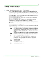
Page 4: ...ct and instruction manual to indicate that there are precautions for safety Indicates that caution is required when handling the equipment This symbol is labeled on the Product to indicate the possibility of dangers such as electric shock on personnel and equipment and also indicate that the user must refer to the User s Manuals for necessary actions In the User s Manuals this symbol is used toget...

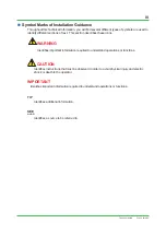
Page 5: ...these icons WARNING Identifies important information required to understand operations or functions CAUTION Identifies instructions that must be observed in order to avoid physical injury and electric shock or death to the operator IMPORTANT Identifies important information required to understand operations or functions TIP Identifies additional information SEE ALSO Identifies a source to be refer...

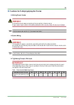
Page 6: ...ard Ground the device following the procedure in this document to prevent from electric shock and to minimize the noise SEE ALSO For earth wiring refer to 3 3 Connecting grounding cable l Tightening Torque of Screws IMPORTANT The tightening torque that the product recommends is showed in the following table However if the tightening torque of the screw is specified in the User s Manuals follow the...

Page 7: ...he fuses for exchange must be the Yokogawa designated fuses l Maintenance CAUTION The maintenance work for the devices described in this manual should be performed only by the educated experts When the device becomes dusty use a vacuum cleaner or a soft cloth to clean it During maintenance put up wrist strap and take other ESD Electrostatic Discharge measures If the existing caution label is dirty...

Page 8: ...10 01EN l Field Power Supply IMPORTANT Do not use output voltage potentiometer n Drawing Conventions Some drawings may be partially emphasized simplified or omitted for the convenience of description Feb 26 2018 00 ...

Page 9: ...ks of Yokogawa Electric Corporation All other company and product names mentioned in this manual are trademarks or registered trademarks of their respective companies We do not use TM or mark to indicate those trademarks or registered trademarks in this manual We do not use logos and logo marks in this manual ...

Page 10: ...Blank Page ...

Page 11: ...ansportation 2 1 2 2 Unpacking 2 4 2 3 Storage 2 5 2 4 Servicing area 2 6 2 5 Installing equipment 2 7 3 Cabling 3 1 3 1 Connecting cables to the cable entry 3 1 3 2 Connecting power cable 3 2 3 3 Connecting grounding cable 3 5 3 3 1 Connecting grounding cable for the enclosure 3 5 3 3 2 Connecting grounding cable to grounding bar for shield lines 3 6 3 4 Connecting signal cable 3 7 3 4 1 Connecti...

Page 12: ...Blank Page ...

Page 13: ...al temperature range bring it without a package keep it within temperature change rate and avoid condensation Keep ambient temperature within operational temperature range and leave it for more than three hours before starting operation Under normal operation the rate of change of ambient temperatures should be within 10 C h All the equipment should be kept out of the rain and direct sunlight by i...

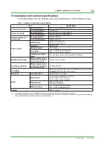
Page 14: ...titude of up to 2000 m Installation category based on IEC 61010 1 1 Category I For YOKOGAWA products category I applies to the device that receives the electric power not more than 33 V AC 70 V DC Category II For YOKOGAWA products category II applies to the device that receives the electric power exceeding 33 V AC or 70 V DC Pollution degree based on IEC 61010 1 2 Environment inside the enclosure ...

Page 15: ...escription IEC EN CSA 61010 2 030 No 1 O Other For measurements performed on circuits not directly connected to MAINS No 2 Measurement category II For measurements performed on circuits directly connected to the low voltage installation No 3 Measurement category III For measurements performed in the building installation No 4 Measurement category IV For measurements performed at the source of the ...

Page 16: ...er when receiving rated AC voltage Withstanding voltage Between power input terminal and protective conductor terminal 1500 V AC for 1 minute Insulation resistance Between power input terminal and protective conductor terminal 20 MΩ 500 VDC Grounding Apply the grounding system which is defined by the rules and standards of the country or the region Shock 2 Transport shock Horizontal 48 m s2 or les...

Page 17: ... specified see below IMPORTANT If the power unit has high output impedance or high wiring impedance the resulting voltage drop flattens the input voltage wave forming a distorted waveform with a low peak value B in the chart below Even if the effective value of the distorted input voltage wave is the same as that specified for a non distorted input voltage wave the voltage across the terminals of ...

Page 18: ...operating voltage range V op 2 V rms V op 2 V rms Figure System operating voltage range n Selecting a power system N IO field enclosure system requires a power supply that satisfies power requirements in accordance with EMC regulations For selection of the power supply unit consult with a power unit manufacturer taking the following points into consideration l Source output capacity Take the follo...

Page 19: ...nterruptible power unit with automatic recovery n Cabling Observe the following when cabling the power unit to the system equipment Protect signal cables from induced noise Protect signal cables from induced noise from high voltage power lines Separate the system power supply from other equipment power supplies using a power distribution board Provide a dedicated breaker for each power supply Labe...

Page 20: ...EC 60364 IEC 62305 and IEC 61000 5 2 can be applied A protective device is to be installed in compliance with the rules and regulations in order to prevent electric shocks caused by a ground fault n Grounding of enclosure Connect the protective conductor terminal outside N IO field enclosure to the protective grounding system Apply the grounding system which is defined by the rules and standards o...

Page 21: ...ect the grounding bar inside the enclosure to the protective grounding system via cable entry F010302 ai Protective conductor terminal M10 bolt Grounding bar Protective grounding system Protective grounding system Power input terminal Cable entry Grounding cable Figure Grounding of enclosure Feb 26 2018 00 ...

Page 22: ...le to separate the protective grounding system of the grounding bar for shield lines from the one of the enclosure system by changing the grounding connection as shown in the figure below SEE ALSO See Section 3 3 2 Connecting grounding cable to grounding bar for shield lines for the cables and terminals Protective grounding system Protective grounding system F010303 ai Protective conductor termina...

Page 23: ...ntry and region should be used between each enclosure and grounding bus inlet When providing lightning arresters on power and signal lines those arresters need to be grounded to the same bus For details see Section 1 4 Noise countermeasures Enclosure Enclosure Enclosure Enclosure Protective grounding system Graunding bus inlet F010304 ai G Protective conductor terminal G G G G Figure Grounding con...

Page 24: ... conduits Shield magnetic field using ferromagnetic substance e g Permalloy Use twisted pair cables Electrostatic induction Equipment maloperation Interference with signals Use shielded signal cables Electrically separate power and signal cables using metallic conduits and separators Lay power and signal cables which intersect at right angles Lightning Interference with signals Equipment maloperat...

Page 25: ...ion Concatenation grounding a lightning arrester and other equipment may cause high tension in each equipment by the product of lightning current from arrester and grounding resistance To prevent from electrification overall connection should be equipotential including the floor and the case of other equipment Protective grounding system F010401 ai Signal cable Signal cable Protective conductor te...

Page 26: ...les of arrester installation n Examples of spark killer installation The following shows how to install a spark killer as a countermeasure against inductive load caused noise Relay contact Power supply F010403 ai Example R 120 Ω C 0 1 to 0 3 μF Example R 120 Ω C 0 1 μF Spark killer N IO field enclosure 100 V AC Fluorescent lamp or fan The spark killer prevents noise caused equipment failure when a...

Page 27: ...intenance work use a wrist strap with a ground wire via a grounding resistance of 1 MΩ Be sure to ground the wrist strap When performing maintenance work on a desk or a table place a conductivity sheet grounded via a grounding resistance of 1 MΩ The maintenance person must wear a wrist strap while performing maintenance work Take any plastic and other materials that can easily be charged away from...

Page 28: ...t from the system grounding for the enclosure F010501 ai Figure Separator used in duct pit n Distance between cables If a separator cannot be used keep a distance between signal cables and power cables The distances between cables due to operating voltages and currents are shown below Table Required distance between Power Shielded signal cables Operating voltage Operating current Distance 240 V AC...

Page 29: ...s Protective grounding system F010503 ai Figure Intersecting cables under pit free access floor n Ambient temperature The ambient temperature where signal and bus cables are laid must be within the range 40 to 55 C n Measures against EMI As a rule avoid laying the cables on the floor However lay them on the floor when there are no ducts and no pits In that case it is required to take measures such...

Page 30: ...original packing n Transportation SEE ALSO See Table Equipment installation specifications in Section 1 1 Installation environment for ambient temperature humidity and impact l Loading Load crates horizontally When loading crates on top of others up to the following number of stacking stages is allowable Table Allowable total number of stacking stages Model Allowable total number of stacking stage...

Page 31: ... magnetic fields n Unloading Prepare special equipment for unloading Avoid unloading outdoor in case of rain l Location for unloading To select a location for safe unloading check that There is ample space for crane and forklift maneuvering Ground is solid The handrails of scaffold can be removed There is enough working space for unpacking at least 2500 mm by 4000 mm Provide a platform if necessar...

Page 32: ... product weights F020101 ai Pad eye 60 Figure How to lift of an enclosure n Carrying This section describes how to carry enclosures l Carrying space passage Carry enclosures into the location of installation without unpacking Determine the passage according to the product s packing size and weight and carrier s size and weight Table Packing size and packing weight of the product Model Packing size...

Page 33: ...o Yes If yes remove them and check the surrounding Damage to equipment interior No Yes If damaged badly inform Yokogawa Condensation or its trace on equipment interior No Yes If yes inform Yokogawa CAUTION Condensation in the enclosure may cause critical trouble in the system Be sure to unpack the equipment indoor under the specified environmental conditions Strictly observe the allowable temperat...

Page 34: ... corrosive gas or salty air may be present SEE ALSO See Section 1 1 Installation environment for permissible temperature humidity and temperature fluctuation of storage area n Storage of packed equipment Store crates horizontally When loading crates on top of others up to the following number of stacking stages is allowable Table Allowable total number of stacking stages Model Allowable total numb...

Page 35: ...e This servicing area is indicated for each equipment This servicing area should be considered when determining the installation location When installing the product on the side of a corridor provide enough space for people to pass by in addition to the space below F020401 ai R800 Unit mm 800 Top view Figure N IO field enclosure servicing area Feb 26 2018 00 ...

Page 36: ... the enclosure on concrete use proper concrete anchor screws When installing the enclosure on a steel plate drill holes and use M10 lock washers and nuts to secure it Provide a heat dissipation space g of at least 100 mm over the top of the enclosure In addition provide a space h under the enclosure which includes a cable bending radius space for cables passed through the cable entry at the bottom...

Page 37: ... the enclosure cables should be connected to the enclosure through cable glands or sealing modules F030101 ai Figure Cable entry at the enclosure s bottom F030102 ai Figure Insertion of power cable into the cable entry n Installation of Roxtec s sealing module When installing the sealing module into the sealing system frame the specialized tool provided by Roxtec enables the quick and safe on site...

Page 38: ...nsulating cover which have low contact resistance little aging F030201 ai Insulation covering inside diameter Hole diameter Lug outside diameter Lug length Figure Solderless crimp on lug l Solderless crimp on lug specifications The solderless lug to use must have the dimensions given in table according to the nominal cross sectional area of the power cable for which the lug is to be used Crimping ...

Page 39: ...p referred to 100 V supply of 2 V or less in the main line viewed from the indoor power distribution board Voltage drop of 2 V or less across this section of wiring Equip ment L m AC wiring 100 V AC 220 V AC High voltage wiring F030202 ai Figure Maximum cable length calculation conditions Maximum power cable length calculation conditions Use the following formula to calculate the maximum power cab...

Page 40: ...s of AC distribution boards l AC Power distribution board The power cables are branched to each unit by way of a circuit breaker Each power system uses three terminals AC and ground ISO M4 to M6 screws Enclosure Enclosure Enclosure Power distribution board 100 120 V AC or 220 240 V AC F030204 ai Figure AC Power distribution board Feb 26 2018 00 ...

Page 41: ...e Ensure to secure the minimum bending radius of the cable The minimum bending radius is either the value shown in the cable manufacturer s specifications or six fold of the cable conductor diameter whichever is bigger should be applied n Grounding cable termination Use solderless lugs for power cables The solderless lug to use must have the dimensions given in table according to the nominal cross...

Page 42: ... for shield lines for more information n Grounding cables Nominal conductor cross sectional area 0 5 to 6 0 mm2 Solid 0 5 to 4 0 mm2 Flexible Temperature rating of cables Enclosure ambient temperature 35 ºC or more n Grounding cable termination Connect the cable with the cable coating stripped without a sleeve The peel off length should be 16 mm Feb 26 2018 00 ...

Page 43: ...he use of twisted pair cables is also recommended for digital signals The twisted pair cable has the following advantages over a solid wire More flexible for easy curving and cabling in limited spaces Signal cables must be clamped so that their weight does not affect terminals Be careful not to apply excessive force to the cable when laying it n When mixing AI and DO in the same multi core cable N...

Page 44: ...ve The specifications of the sleeve differ depending on the cable thickness Provide cable termination according to the following figure and tables L1 L2 L1 Sleeve with insulating cover Core Cable Peel off length F030501 ai Sleeve without insulating cover Figure Cable termination Table When sleeves with insulating cover are used Nominal cross sectional area mm2 Peel off length mm Sleeve dimensions ...

Page 45: ...ing bar for a shield line in the enclosure n Shield lines Nominal conductor cross sectional area 0 5 to 6 0 mm2 Solid 0 5 to 4 0 mm2 Flexible Temperature rating of cables Enclosure ambient temperature 35 ºC or more n Shield lines termination Connect the cable with the cable coating stripped without a sleeve The peel off length should be 16 mm Feb 26 2018 00 ...

Page 46: ...single mode optical fiber 2 Required number of cores 2 Max length 50 km 1 If attenuation of light in the optical ESB bus 5 to 50 km connection is less than 3 dB attenuate to 3 dB by using an attenuator 2 JIS C 6835 SSMA 9 3 125 or IEC 607932 50B1 1 type Lay fiber optic cables according to the manufacturer s cable handling precautions such as allowable bending radius l N ESB bus for CENTUM VP Trans...

Page 47: ...lled number of equipment heating value by the maximum number of units installed is listed n Actual power on In Rush current of each component The following shows an example of actual in rush current measurement data Table System equipment power on In Rush current Model Name In Rush current A 100 120 V AC 220 240 V AC A2NN70D N IO field enclosure 70 92 S2NN70D N IO field enclosure 70 92 Input curre...

Page 48: ...ons in general the temperature inside of the enclosure is about 10 C higher than the temperature outside the enclosure Note Random failures within the recommended replacement intervals may occur in some parts IMPORTANT The reliability and life span of electronic equipment greatly depend on the operating environment It is essential for ensuring reliable operation and prolonged life span that the eq...

Page 49: ...e Estimate the ambient temperature around the power supply unit by roughly 10 C higher than the outside of the enclosure l Limited life parts of the N IO field enclosure for ProSafe RS Table Periodic replacement parts having defined life spans Part names Part numbers Recommended replacement cycle Replacement by user Remarks Field power supply S9201UD 8 years Yes Average ambient temperature 40 C or...

Page 50: ...ensation or traces on enclosure interior exterior No discoloration or rust on enclosure interior exterior No condensation or traces on cards disconnect cards on the upper middle and lower stands and left and right sides of the enclosure to check that there is no condensation on the cards or defects anywhere in the enclosure No dust remaining inside cabinet It is recommended that you turn on the po...

Page 51: ...i TI 30A30A10 01EN Revision Information l Title Installation Guidance for N IO field enclosure l Manual No TI 30A30A10 01EN Feb 2018 1st Edition Newly published Feb 26 2018 00 ...

Page 52: ...Written by Yokogawa Electric Corporation Published by Yokogawa Electric Corporation 2 9 32 Nakacho Musashino shi Tokyo 180 8750 JAPAN Subject to change without notice ...

Reviews: