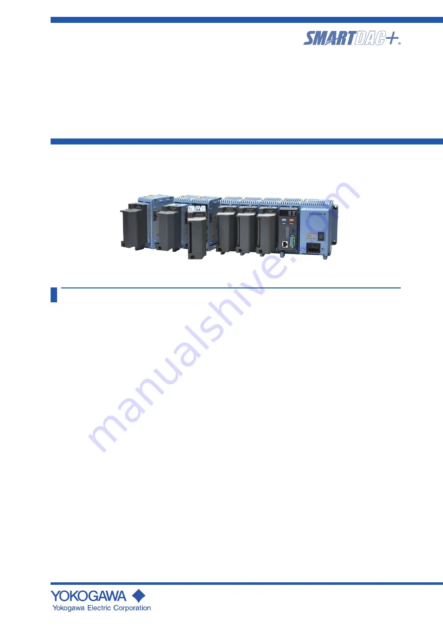
Data Acquisition System GM
First Step Guide
IM 04L55B01-02EN
4th Edition
Contents
Introduction ................................................................................. 2
Checking the Package Contents ................................................. 3
MODEL and SUFFIX Codes ....................................................... 4
Standard Accessories ................................................................. 5
Module Notation .......................................................................... 6
GM Overview ............................................................................. 6
GM Configuration ........................................................................ 6
Module Version and Notes on Linking .......................................... 6
Channel Names .......................................................................... 7
Operating Procedure ........................................................8
Basic Operation ..............................................................10
Names of the GM10 Parts ..........................................................10
Configuring the GM via Ethernet Communication .......................10
Configuring the GM via USB Communication .............................12
Starting to Measure and Record .................................................12
Installation.......................................................................13
Installation Location ....................................................................13
Installation Procedure .................................................................13
Unit External Dimensions (Unit: mm) ...........................................13
Installing on a Desktop or Floor.................................................. 14
Mounting on a DIN Rail .............................................................. 14
Mounting on a Wall .................................................................... 14
Wiring ..............................................................................15
Precautions to Be Taken While Wiring ........................................16
Removing and Attaching a Terminal Cover .................................16
Removing and Attaching a Terminal Block ..................................16
Wiring Procedure .......................................................................17
Internal dimensions of the M3 screw terminal (unit: mm) .............17
Wiring the Clamp Terminal ..........................................................17
Wiring to a GX90XA Analog Input Module ..................................17
Wiring to a GX90XD Digital Input Module....................................19
Wiring to a GX90YD Digital Output Module .................................19
Wiring to a GX90WD Digital I/O Module .................................... 20
Wiring to a GX90XP Pulse Input Module.................................... 20
Wiring to a GX90YA Analog Output Module ............................... 20
Wiring to a GX90UT PID Control Module ................................... 20
Connecting to the RS-422/485 Connector
(/C3 option) ............................................................................21
Connecting to the USB Port .......................................................21
Connecting to the Ethernet Port .................................................21
Wiring the Power Supply ........................................................... 22
Turning the Power On and Off ................................................... 23
Connecting GX90EX Expansion Modules ................................. 23
Bluetooth Connection Procedure (/C8 option) ............................ 24
User’s
Manual


