
IM 05P08D31-11EN page 1/12
Contents
1. Safety Precautions
2. Model and Suffix Codes
3. How to Install
4. Hardware Specifications
5. How to Connect Wires
6. Terminal Wiring Diagrams
Introduction
Thank you for purchasing the UT32A-D Digital Indicating Controller (Dual-loop type).
This operation guide describes the basic operations of the UT32A-D. The guide
should be provided to the end user of this product.
Be sure to read this operation guide before using the product in order to ensure
correct operation.
For details of each function, refer to the electronic manual. Before using the product,
refer to the table of Model and Suffix Codes to make sure that the delivered product
is consistent with the model and suffix codes you ordered. Also make sure that the
following items are included in the package.
• Digital Indicating Controller (the model you ordered)
..............................
x1
• Set of Brackets ........................................................................................
x1
• Unit Label (L4502VZ)
..............................................................................
x1
• Tag Label (L4502VE)
..............................................................................
x1
(Only when ordered.)
• Operation Guide (this document)
............................................................
x6 (A3 size)
(Installation and Wiring, Initial Settings, Operations, and Parameters)
l
Target Readers
This guide is intended for the following personnel;
• Engineers responsible for installation, wiring, and maintenance of the equipment.
• Personnel responsible for normal daily operation of the equipment.
1. Safety Precautions
The following symbol is used on the instrument. It indicates the possibility of injury
to the user or damage to the instrument, and signifies that the user must refer to the
operation guide or user’s manual for special instructions. The same symbol is used in
the operation guide and user’s manual on pages that the user needs to refer to, together
with the term “WARNING” or “CAUTION.”
WARNING
Calls attention to actions or conditions that could cause serious
or fatal injury to the user, and indicates precautions that should be
taken to prevent such occurrences.
CAUTION
Calls attention to actions or conditions that could cause injury to
the user or damage to the instrument or property and indicates pre-
cautions that should be taken to prevent such occurrences.
AC
AC/DC
The equipment wholly protected by double insulation or reinforced insulation.
Functional grounding terminals
(Do not use this terminal as a protective grounding terminal).
Note
Identifies important information required to operate the instrument.
■
Warning and Disclaimer
(1) YOKOGAWA makes no warranties regarding the product except those stated in
the WARRANTY that is provided separately.
(2) The product is provided on an "as is" basis. YOKOGAWA assumes no liability to
any person or entity for any loss or damage, direct or indirect, arising from the
use of the product or from any unpredictable defect of the product.
■
Safety, Protection, and Modification of the Product
(1) In order to protect the system controlled by this product and the product itself,
and to ensure safe operation, observe the safety precautions described in the
operation guide. Use of the instrument in a manner not prescribed herein may
compromise the product's functions and the protection features inherent in the
device. We assume no liability for safety, or responsibility for the product's quality,
performance or functionality should users fail to observe these instructions when
operating the product.
(2) Installation of protection and/or safety circuits with respect to a lightning
protector; protective equipment for the system controlled by the product and the
product itself; foolproof or fail-safe design of a process or line using the system
controlled by the product or the product itself; and/or the design and installation
of other protective and safety circuits are to be appropriately implemented as the
customer deems necessary.
(3) Be sure to use the spare parts approved by YOKOGAWA when replacing parts
or consumables.
(4) This product is not designed or manufactured to be used in critical applications
that directly affect or threaten human lives. Such applications include nuclear
power equipment, devices using radioactivity, railway facilities, aviation
equipment, air navigation facilities, aviation facilities, and medical equipment.
If so used, it is the user’s responsibility to include in the system additional
equipment and devices that ensure personnel safety.
(5) Modification of the product is strictly prohibited.
(6) This product is intended to be handled by skilled/trained personnel for electric devices.
(7) This product is UL Recognized Component. In order to comply with UL standards,
end-products are necessary to be designed by those who have knowledge of the
requirements.
WARNING
l
Power Supply
Ensure that the instrument’s supply voltage matches the voltage
of the power supply before turning ON the power.
l
Do Not Use in an Explosive Atmosphere
Do not operate the instrument in locations with combustible
or explosive gases or steam. Operation in such environments
constitutes an extreme safety hazard. Use of the instrument in
environments with high concentrations of corrosive gas (H
2
S,
SO
X
, etc.) for extended periods of time may cause a failure.
l
Do Not Remove Internal Unit
The internal unit should not be removed by anyone other than
YOKOGAWA's service personnel. There are dangerous high voltage
parts inside. Additionally, do not replace the fuse by yourself.
l
Damage to the Protective Construction
Operation of the instrument in a manner not specified in the
operation guide may damage its protective construction.
CAUTION
This instrument is an EMC class A product. In a domestic environ-
ment this product may cause radio interference in which case the
user needs to take adequate measures.
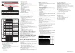
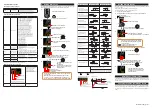
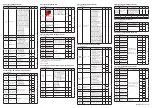
2. Model and Suffix Codes
■
UT32A-D «Standard Code Model»
Model
Suffix code
Option
code
Description
UT32A
Digital Indicating Controller (Power supply: 100-240
V AC) (provided with 3 DIs, and 3 DOs)
Type 1:
Basic
control
-D
Dual-loop type
Type 2:
Functions
0
None
1
RS-485 communication (Max. 38.4 kbps, 2-wire/4-wire)
Type 3:
Open networks
0
None
3
CC-Link communication (with Modbus master function) (*2)
Display language (*1)
-1
English (Default. Can be switched to other language by the setting.)
-2
German (Default. Can be switched to other language by the setting.)
-3
French (Default. Can be switched to other language by the setting.)
-4
Spanish (Default. Can be switched to other language by the setting.)
Case color
0
White (Light gray)
1
Black (Light charcoal gray)
Fixed code
-00
Always "-00" (for Standard Code Model)
Option codes
/HA
Heater break alarm (*2)
/DC
Power supply 24 V AC/DC
/CT
Coating (*3)
/CV
Terminal cover
/MDL
Mount on DIN rail (without the display parts
and keys) (please see the Operation Guide IM
05P08D81-11EN.)
*1: English, German, French, and Spanish are available for the guide display.
*2: The /HA option can be specified when the Type 2 code is “0.”
*3: When the /CT option is specified, the UT32A does not conform to the safety standards (UL
and CSA) and CE marking (Products with /CT option are not intended for EEA-market).
■ Customized Product
For customized product, the product is identified by the option code of /S# (where ‘#’
is a number).
Contact your supplier in case your instrument has option /S#, and you are not
in the possession of FX1-[Model code]-S# or IM [Model code]-S# (where [Model
code] means, for example, UT55A).
■
Accessories (sold separately)
The following is an accessory sold separately.
• LL50A Parameter Setting Software
Model
Suffix code
Description
LL50A
-00
Parameter Setting Software
• External Precision Resistor
Model
Suffix code
Description
X010
See the General Specifications (*) Resistance Module
*: Necessary to input the current signal to the voltage input terminal.
• Terminal Cover
For UT32A: Model UTAP002
• Manuals
Note: Manuals can be downloaded from a website. URL: http://www.yokogawa.com/ns/ut/im/
• Brackets
Part number: L4502TP (2 pcs for upper and lower sides)
WARNING
Be sure to turn OFF the power supply to the controller before in-
stalling it on the panel to avoid an electric shock.
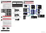
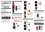
■
Mounting the Instrument Main Unit
Provide an instrumented panel steel sheet of 1 to 10 mm thickness.
After opening the mounting hole on the panel, follow the procedures below to install
the controller:
1) Insert the controller into the opening from the front of the panel so that the
terminal board on the rear is at the far side.
2) Set the brackets in place on the top and bottom of the controller as shown in the
figure below, then tighten the screws of the brackets. Take care not to overtighten
them.
Bracket
(top mounting hardware)
Terminal board
Bracket
(bottom mounting hardware)
Panel
Insert a screwdriver into the
brackets to tighten the screws.
Direction to insert the
controller
Appropriate
tightening torque:
0.25 N
•
m
Insert the controller
into the opening at
the front of the panel.
CAUTION
• Tighten the screws with appropriate tightening torque within 0.25
N•m. Otherwise it may cause the case deformation or the bracket
damage.
• Make sure that foreign materials do not enter the inside of the
instrument through the case’s slit holes.
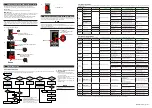
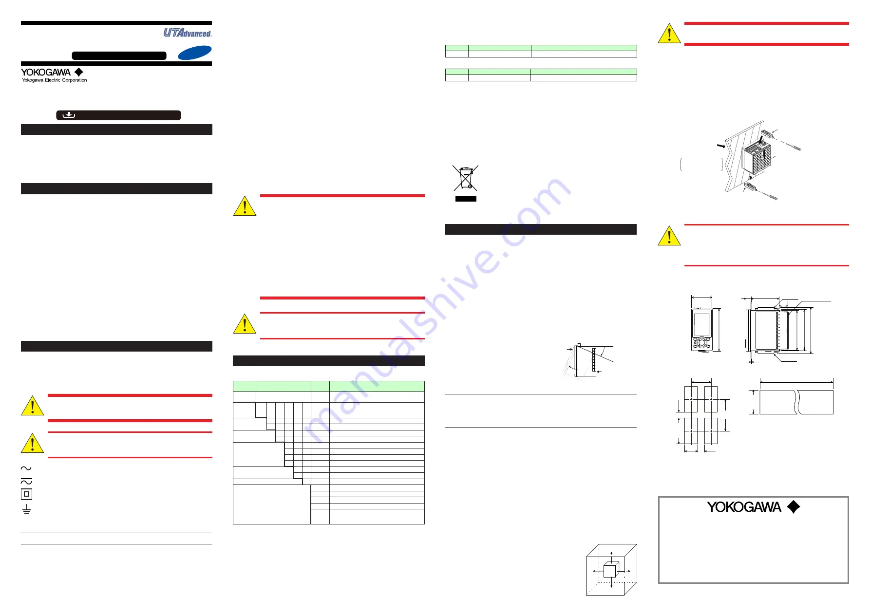
■
External Dimensions and Panel Cutout Dimensions
[(N-1)×48+45]
+0.6
0
65 (2.56)
48 (1.89)
11 (0.43)
UT32A
1 to 10 mm (0.04 to 0.39 inch) (panel thickness)
Bracket
Bracket Terminal cover
94.6 (3.72)
96 (3.78)
105.2 (4.14)
Unit: mm (approx. inch)
70 (2.76)
min.
(25)
145 (5.71)
min.
+0.6
0
45
(53) (2.09)
+0.8
0
92
• General mounting
• Side-by-side close mounting
20 (0.79)
91.6 (3.61)
“N” stands for the number of controllers to be
installed.
However, the measured value applies if N
≥
5.
Normal tolerance:
±(value of JIS B 0401-1998 tolerance class IT18)/2
+0.03
0
(3.62 )
+0.02
0
(1.77 ) (0.98)
+0.8
0
92
+0.03
0
(3.62 )
([(N-1)×1.89+1.77] )
+0.02
0
Operation
Guide
IM 05P08D31-11EN
UT32A-D
Digital Indicating Controller
(Dual-loop, Panel mount type)
Operation Guide
This operation guide describes installation, wiring, and other tasks required to make the
controller ready for operation.
3rd Edition : Mar. 2018
Installation and Wiring
For details of the each function, refer to the electronic manual. Manuals can be
downloaded or viewed at the following URL.
Functional
Enhancement
http://www.yokogawa.com/ns/ut/im/
«Standard Code Model»
www.yokogawa.com/ns
YOKOGAWA ELECTRIC CORPORATION
Network Solutions Business Division
2-9-32, Naka-cho Musashino-shi, Tokyo 180-8750 JAPAN
YOKOGAWA CORPORATION OF AMERICA
Head office and for product sales
2 Dart Road, Newnan, Georgia 30265, USA
YOKOGAWA EUROPE B.V.
Headquarters
Euroweg 2, 3825 HD Amersfoort, THE NETHERLANDS
All Rights Reserved, Copyright © 2015 Yokogawa Electric Corporation
■
Protection of Environment
Waste Electrical and Electronic Equipment (WEEE), Directive
This is an explanation of how to dispose of this product based on Waste Electrical
and Electronic Equipment (WEEE), Directive. This directive is only valid in the EU.
● Marking
This product complies with the WEEE Directive marking
requirement. This marking indicates that you must not discard
this electrical/electronic product in domestic household waste.
● Product Category
With reference to the equipment types in the WEEE directive,
this product is classified as a “Small equipment” product.
Do not dispose in domestic household waste. When disposing
products in the EU, contact your local Yokogawa Europe B.V. office.
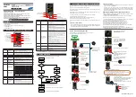
3. How to Install
■
Installation Location
The instrument should be installed in indoor locations meeting the following
conditions:
• Instrumented panel
This instrument is designed to be mounted in an instrumented panel. Mount the
instrument in a location where its terminals will not inadvertently be touched.
• Well ventilated locations
Mount the instrument in well ventilated locations to prevent the instrument’s inter-
nal temperature from rising.
However, make sure that the terminal portions are not exposed to wind. Exposure
to wind may cause the temperature sensor accuracy to deteriorate. To mount mul
-
tiple indicating controllers, see the external dimensions/panel cutout dimensions
which follow.
If mounting other instruments adjacent to the instrument, comply with
these panel cutout dimensions to provide sufficient clearance between the instruments.
• Locations with little mechanical vibration
Install the instrument in a location subject to little mechanical vibration.
• Horizontal location
Mount the instrument horizontally and
ensure that it is level, with no inclination
to the right or left.
Front panel
of controller
Keep this angle
within 30°
Rear of
controller
30°
Note
If the instrument is moved from a location with low temperature and low humidity
to a place with high temperature and high humidity, or if the temperature changes
rapidly, condensation will result. Moreover, in the case of thermocouple inputs,
measurement errors will result. To avoid such a situation, leave the instrument in the
new environment under ambient conditions for more than 1 hour prior to using it.
Do not mount the instrument in the following locations:
• Outdoors
• Locations subject to direct sunlight or close to a heater
Install the instrument in a location with stable temperatures that remain close to an
average temperature of 23°C. Do not mount it in locations subject to direct sunlight
or close to a heater. Doing so adversely affects the instrument.
• Locations with substantial amounts of oily fumes, steam, moisture, dust, or
corrosive gases
The presence of oily fumes, steam, moisture, dust, or corrosive gases adversely
affects the instrument. Do not mount the instrument in locations subject to any of
these substances.
• Areas near electromagnetic field generating sources
Do not place magnets or tools that generate magnetism near the instrument. If the
instrument is used in locations close to a strong electromagnetic field generating
source, the magnetic field may cause measurement errors.
• Locations where the display is difficult to see
The instrument uses an LCD for the display unit, and this can be difficult to see
from extremely oblique angles. Mount the instrument in a location where it can be
seen as much as possible from the front.
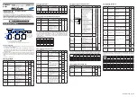
• Areas close to flammable articles
Absolutely do not place the instrument directly on flam-
mable surfaces. If such a circumstance is unavoidable
and the instrument must be placed close to a flammable
item, provide a shield for it made of 1.43 mm thick plated
steel or 1.6 mm thick unplated steel with a space of at
least 150 mm between it and the instrument on the top,
bottom, and sides.
• Areas subject to being splashed with water
150 mm
150 mm
150 mm
150 mm


