YoraHome SILVERBACK 6060, User Manual
Introducing the YoraHome SILVERBACK 6060— a powerful and versatile machine built to revolutionize your crafting projects. Unlock its full potential with the comprehensive service manual and user guide, available for free download at 88.208.23.73:8080. Seamlessly navigate through the intricacies of this exceptional product to maximize your creative endeavors.
Share
Download


Reviews:
No comments
Related manuals for SILVERBACK 6060
D2000
Brand: WABECO Pages: 89
EC-400
Brand: Haas Pages: 2
Elite E-1236VS
Brand: Jet Pages: 8
JWL-1236
Brand: Jet Pages: 20
JWL-1440VS
Brand: Jet Pages: 32
JML-1014VS
Brand: Jet Pages: 5
REVO 10
Brand: Laguna Tools Pages: 24
REVO 18
Brand: laguna Pages: 54
ProtoMax
Brand: Omax Pages: 2
D4000
Brand: WABECO Pages: 78
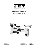
JML-1014
Brand: Jet Pages: 12

BDB-1340A
Brand: Jet Pages: 20
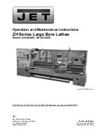
ZH Series
Brand: Jet Pages: 104
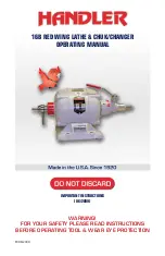
Red Wing 16B
Brand: Handler Pages: 16
NOVA TL1200
Brand: Teknatool Pages: 14
KC-0712ML
Brand: King Canada Pages: 7
24062
Brand: Proxxon Pages: 32

BL330E
Brand: Anhui Pan-sino Pages: 26


