background image

PAGE 1

I - Ship ping And Pack ing List

Package 1 of 2 contains:

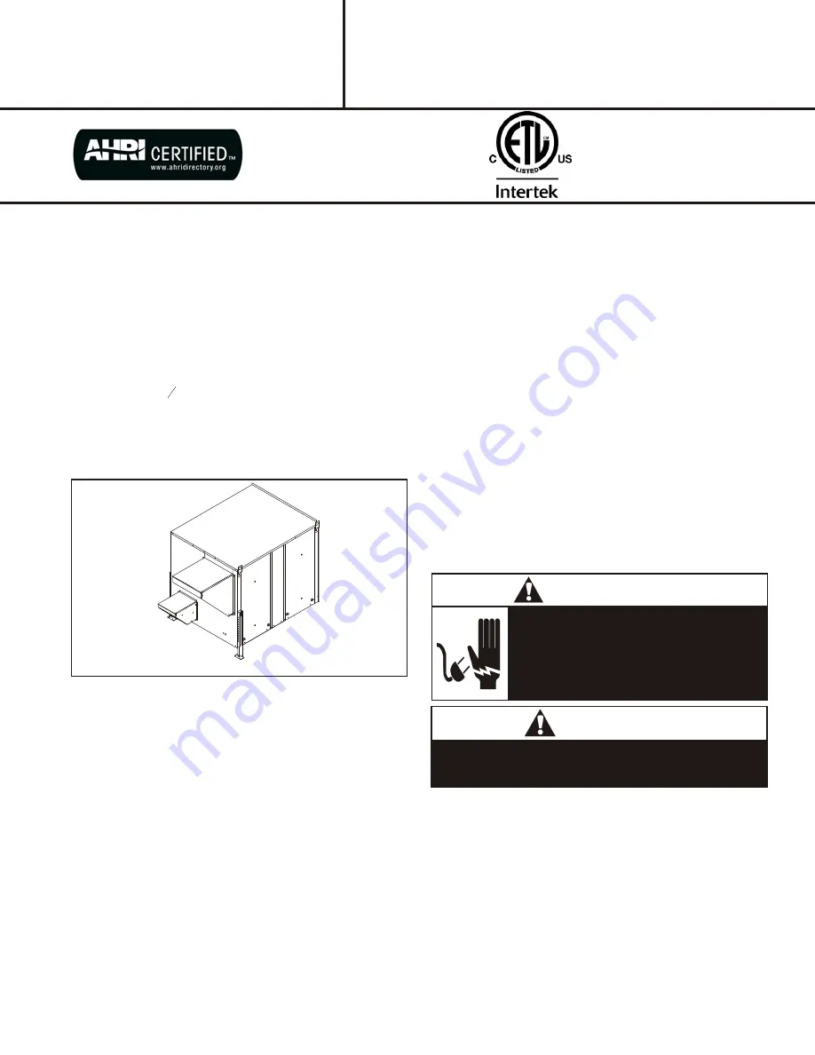
1 - Energy Recovery Ventilator Assembly
1 - Outdoor Fresh Air Hood w/ Filter
1 - Outdoor Exhaust Hood w/ Barometric Dampers

Package 2 of 2 contains:

1 - Balancing Damper Assembly
1 - Platform Support Rail
2 - Door Panels
1 - Bag Assembly

  1 - Roll of ¾" x 1 ¼" gasket 
  1 - 272" of 

1

8

" x ½"  gasket 

  1 - Field Wiring Harness for Low Voltage with 
       ECO 1001 economizer control board
10 - #14 Screws 
30 - #10 x ½" Gold Screws 
  1 - Installation Instructions 

Recovery Wheel Mode

The Recovery Wheel mode is accomplished by two
blowers providing continuous exhaust of stale indoor air
and replacement by equal amount of outdoor air. Energy
recovery is achieved by slowly rotating the energy
recovery wheel within the cassette frame work. In winter,
the UERV adsorbs heat and moisture from the exhaust air
stream during one half of a complete rotation and gives
them back to the cold,drier intake air supply during the
other half rotation. In summer, the process is automatically
reversed. Heat and moisture are absorbed from incoming
fresh air supply and transferred to the exhaust air stream.
This process allows outdoor air ventilation rates to be
increased by factors of three or more without additional
energy penalty or increase in size of heating or air
conditioning systems.

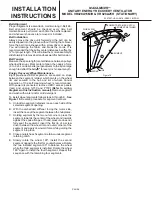
VI - Rig ging Unit For Lift ing

1.

Maximum weight of unit is — 750 Lbs. (Crated)

2.

Remove crating. Then remove access panel to

retrieve bag assembly. Replace access panel.

3.

All panels must be in place for rigging.

4.

Lifting lugs are supplied with the unit. Loosen machine
bolts and rotate lifting lug.

CAUTION

Danger of sharp metallic edges. Can cause injury.
Take care when servicing unit to avoid accidental
contact with sharp edges.

WARNING

Electric shock hazard. Can cause injury
or death. Before attempting to perform
any service or maintenance, turn the
e l e c t r i c a l   p o w e r   t o   u n i t   O F F   a t
disconnect switch(es). Unit may have
multiple power supplies.

MAXA-MI$ER

Ô

UNITARY ENERGY RECOVERY VENTILATOR

MODEL VR028A15M/H & VR028A25H  (STATIONARY) 

 INSTALLATION

INSTRUCTIONS

5257527-UAI-A-0616 / R28A-18YSDW

ETL Certified per UL 1995
and CSA 22.2

E n e r g y   r e c o ve r y   C O M P O N E N T
certified to the AHRI Air-to-Air Energy 
Recovery Ventilation Equipment
Certification Program in accordance
w ith AHRI Standard 1060-2000.
Actual performance in packaged
equipment may vary.

UERV

II - Ship ping Dam age

Check unit for shipping damage. Receiving party should
contact last carrier immediately if shipping damage is
found.

III - Gen eral

These instructions are intended as a general guide and do
not supersede local codes in any way. Authorities having
jurisdiction should be consulted before installation.

IV - Re quire ments

When installed, the unit must be electrically wired and
grounded in accordance with local codes or, in absence of
local codes, with the current National Electric Code,
ANSI/NFPA No. 70.

V  -  Ap pli ca tion

Unitary Energy Recovery Ventilator (UERV) are used with
15 to 30 ton rooftop units 

equipped with a balancing

damper assembly.

 These wheels conserve energy by

mixing warmer air with cooler air in the following manner:

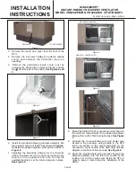
VII  -  In stal la tion

1.

Disconnect all power to the rooftop unit.

Note: Ensure that no power source is connected to the

unit. If the economizer is installed and power is
applied, de-energize all power sources to the unit
and use Lockout - Tag-out procedures. There may
be multiple power inputs to unit, so validate that all 
power sources are de-energized and tagged.

2.

Remove the rooftop units horizontal and return air
access panels. Remove and discard any hoods,
power exhaust equipment or economizer.  

See Figure 

1.

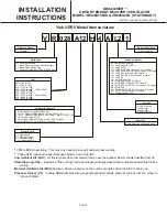
Summary of Contents for VR028A15H

Page 1: ...ontact with sharp edges WARNING Electric shock hazard Can cause injury or death Before attempting to perform any service or maintenance turn the electrical power to unit OFF at disconnect switch es Unit may have multiple power supplies MAXA MI ERÔ UNITARY ENERGY RECOVERY VENTILATOR MODEL VR028A15M H VR028A25H STATIONARY INSTALLATION INSTRUCTIONS 5257527 UAI A 0616 R28A 18YSDW ETL Certified per UL ...

Page 2: ... damper frame within reach of field wiring harness See Figure 7 9 Connect the communication wire and power wire located in the accessory wiring bundle in the RTU return air section to the proper terminals on the economizer control board See SSE field harness diagram at the back of this manual See Figure 8 10 Route the provided field wiring harness through the balancing damper into the return air s...

Page 3: ...as the legs will have to be adjusted once the unit is finally set in place 14 Locate provided roll of x 1 gasket material Apply gasket down the center post of the UERV as well as between the platform support rail and adaptor panel 15 Remove screw from the top panel of the RTU in order to enable lifting the top panel of the RTU up at least 2 Note An equipment support or pressure treated 2x6x60 piec...

Page 4: ...transfer surface and laminar flow through the wheel causes this constant flow of recovered energy to represent up to 85 of the difference in total energy contained within the two air streams Sensible and latent heat are the two components of total heat Sensible heat is energy contained in dry air and latent heat is the energy contained within the moisture of the air The latent heat load from the o...

Page 5: ...hould be removed Also if system check out is being conducted at low ambient temperatures technician should be aware that this kit can cause system not to operate 4 Verify that the UERV 3 three phase blower motors are phased sequentially ensuring correct rotation and operation a Disconnect power b Reverse any two field power leads to the UERV c Reapply power MAXA MI ERÔ UNITARY ENERGY RECOVERY VENT...

Page 6: ... rear and unplug J150 and P150 Refer to wiring diagrams in this instruction manual Remove segment and wash with water and or mild detergent To install wheel segments follow steps A through E See Figure 15 Reverse procedure for segment removal A Unlock two segment retainers one on each side of the selected segment opening B With the embedded stiffener facing the motor side insert the nose of the se...

Page 7: ...P models L5 LAK SSJ not used on P models L6 LAK SSJ PS not used on P models L7 LAK PS L8 LAK MOA and PS M1 Motorized Outside Air MOA M2 MOA SSJ not used on P models M3 MOA SSJ PS PS not used on P models M4 MOA PS S1 Stop Start Job SSJ not used on P models S2 SSJ PS not used on P models P1 Pressure Sensor PS Voltage 2 208 230v 3ph 4 460v 3ph 5 575v 3ph 9 208 320v 1ph Duct Type A No Selection on Roo...

Page 8: ...1 04 1 09 1 09 1 09 1 08 1 05 0 99 0 90 0 82 0 75 0 89 0 88 0 87 0 85 0 81 0 75 0 66 0 59 0 5 0 69 0 68 0 65 0 62 0 57 0 5 0 42 0 35 0 25 0 00 0 20 0 40 0 60 0 80 1 00 1 20 1 40 1500 1600 1700 1800 2000 2200 2400 2600 2800 SCFM Equation of line SCFM PD 0 01 0 00036 TABLE 1 PRESSURE DROP in of W C R28 Series 1100 RPM 1000 RPM 900 RPM 800 RPM ...

Page 9: ...PAGE 9 ...

Page 10: ...r Harness J151 Jack Exhaust Air Motor Harness P153 Plug Field Harness P160 Plug Damper Intake Motor Harness P161 Plug Damper Exhaust Motor Harness RS 1 Rotation Sensor Optional S26 Switch Low Ambient Optional S51 Switch Door S52 Switch Damper Intake S53 Switch Damper Exhaust SD Smoke Detector Optional SSJ Climate Smart Board Optional T27 Transformer Control T28 Transformer Step down Optional TB37 ...

Page 11: ... n u r e p o r p r o f l a n i m r e t e g a t l o v e v i t c e l e S 4 h c t i w s t n e i b m a w o l l a n o i t p O 5 r e p m a d e k a t n i d e z i r o t o m l a n o i t p O 6 t r a m S e t a m i l C l o r t n o c g o j d n a t r a t s p o t s l a n o i t p O 7 t i n u p o t f o o r h t i w t c e n n o c o t d e d i v o r p s s e n r a h r e t p a d a g n i h c t a M 8 r e p m a d t s u a h...

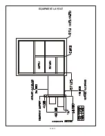
Page 12: ...PAGE 12 EQUIPMENT LAYOUT ...

Page 13: ...h an ERV II SE Procedures to Backup Restore 1 Once the packaged unit is powered up the 120 second startup delay begins Once the delay expires there may or may not be a Start Up delay displayed To cancel the second time delay press the Cancel button for six seconds See Figure 1 Startup Figure 1 Update Figure 2 Backup Figure 3 2 Once the control is out of time delay mode press the Joystick down thro...

Page 14: ...ed past you return by pressing the joy stick lever up until the Update screen appears Screen will read Contrler Controller Update Enter Cancel Buttons Figure 6 View Ver Figure 7 LoadFirm Figure 8 Confirm Figure 9 USB OK Figure 4 4 Press ENTER Screen will read View Ver Version Load Firm Backup 5 Toggle Joy stick down so the arrow is next to Load Firm 6 Press ENTER Screen shows software versions pre...

Page 15: ...E unit control 1 Scroll through menus by pressing down on joystick Status Alarms Summary Commission Econ Economizer Enable Make sure this is set to Yes ERV En Figure 11 Econ En Figure 10 2 Scroll through menus by pressing down on joystick Status Alarms Summary Commission PowerEx ERV Enable Make sure this is set to Yes 3 The economizer minimum setting must be set at 50 or greater Status Alarms Summ...

Page 16: ...actor Start Up Mechanic q Inspect the unit for transit damage and report any damage on the carrier s freight bill q Check model number to insure it matches the job requirements q Install field accessories and unit adapter panels as required Follow accessory and unit installation manuals q Verify field wiring including the wiring to any accessories q Check all multi tap transformers to insure they ...

Reviews: