background image

GENERAL

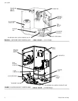
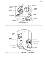
These outdoor heat pump units are designed to be connected
to a matching UPG indoor coil with sweat connection lines. They
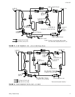
are equipped with a solid core filter-drier located in the dis-
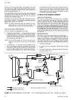
charge line, a high pressure switch, a high temperature switch
(14 SEER models only). The units are factory charged with
refrigerant for a matching indoor coil plus 15 feet of field
supplied line. The outdoor unit is designed to be placed along-
side or at the back of the home, remote from the indoor coil.
The outdoor unit has been factory run-tested and all compo-
nents of the system are ready for easy, immediate installation.

INSPECTION

Check the unit thoroughly for shipping damage. Unusually
rough handling during shipment may loosen  fan motors, com-
pressors, or other components. Be sure that the unit is ready
to operate before installing it. If there is damage, file a claim
with the shipper. See Local Distributor for more information.

REFERENCE

Use this instruction in conjunction with the instructions for the
appropriate indoor unit, air moving system and accessories.

Installer should pay particular attention to the words NOTE,
CAUTION and WARNING.

NOTES are intended to clarify or make the installation easier.

CAUTIONS identify procedures which, if not followed carefully,
could result in personal injury, property damage or product
damage.

WARNINGS are given to alert the installer that severe personal
injury, death or equipment damage may result if installation
procedures are not followed properly.

NOMENCLATURE

LIMITATIONS

CAUTION: The manufacturer is not responsible for the

performance of a mismatched system. The out-
door unit must be installed with a compatible
indoor unit as designated in the specification
data or in the Directory of Certified Unitary Heat
Pumps published by the Air Conditioning and
Refrigeration Institute. Using unmatched com-
ponents may not only affect the performance of
the system, but may also void the warranty of
the equipment.

Do not install any coil in a furnace which is to
be operated during the heating season without
attaching the refrigerant lines to the coil. Allow-
ing the coil charge to enter the refrigerant lines
prevents excessive refrigerant pressure build-
up and possible coil damage.

The unit should be installed in accordance with all national and
local codes and regulations which govern the installation of this
type of equipment. In lieu of local codes, the equipment should
be installed in accordance with the National Electric Code, and
in accordance with the recommendations made by the National
Board of Fire Underwriters.

Limitations for the indoor unit, coil and appropriate accessories
must also be observed.

The outdoor unit must not be installed with any duct work in the air
stream. The outdoor fan is the propeller type and is not designed
to operate against any additional external static pressure.

The maximum and minimum conditions for operation must be
observed to assure a system that will give maximum perform-
ance with minimum service.
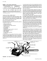
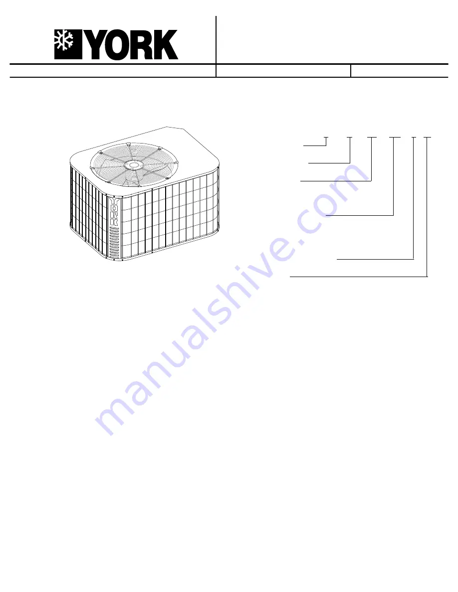
042 = 42,000 Btuh
048 = 48,000 Btuh
060 = 60,000 Btuh

INSTALLATION INSTRUCTION

Supersedes: 515.16-N3Y Coded 1097

515.16-N3Y (298)

OUTDOOR 

SPLIT-SYSTEM HEAT PUMPS

1.5 TO 5 TONS

® 

MODELS E*RA (1 & 3 Ø), E*RC and E*RE

10, 12, 14 SEER

035-15754

                                         E          1         RA       036      S    06

Product Category

E = Heat Pump, Outdoor Unit

1 = 1st Generation

Product Generation

Product Identifier

RA = 10 SEER Split System Heat Pump
RC = 12 SEER Split System Heat Pump
RE = 14 SEER Split System Heat Pump

Nominal Cooling Capacity

018 = 18,000 Btuh
024 = 24,000 Btuh
030 = 30,000 Btuh
036 = 36,000 Btuh

Refrigerant Line Connections

S = Sweat Connect

Voltage Code

06 = 208/230-1-60
25 = 208/230-3-60
46 = 460-3-60 

Summary of Contents for E1RA Series

Page 1: ...or in the Directory of Certified Unitary Heat Pumps published by the Air Conditioning and Refrigeration Institute Using unmatched com ponents may not only affect the performance of the system but may also void the warranty of the equipment Do not install any coil in a furnace which is to be operated during the heating season without attaching the refrigerant lines to the coil Allow ing the coil ch...

Page 2: ...due to wind chill effect Provide ample clearance from shrubs to allow adequate air to pass across the outdoor coil without leaves or branches being pulled into the coil The outdoor unit may never go into the defrost cycle even with minor frost build up during the daytime in some areas of the United States if it is placed on the south side of the residence with no shade However the heat pump may lo...

Page 3: ...ubing must be done with care to obtain reliable trouble free operation 1 Selection of proper refrigerant tubing grade and size 2 Refrigerant line routing cutting and fitting 3 Insulating the vapor line 4 Proper preparation of joint connections 5 Reassembling cleaning and brazing the joint connections 6 Connecting the refrigerant lines to the indoor coil and outdoor unit 7 Pressure leak test all jo...

Page 4: ... Recommendations and Refrigerant Line Length for vapor and liquid line sizing cali bration of liquid line pressure loss or gain determination of vapor line velocity elevation limitations orifice connections system charging traps etc Total line lengths are limited to 75 feet due to the storage capacity of the accumulator Systems with total line lengths over 50 feet must be provided with 1 Low Volta...

Page 5: ...t for volts frequency phase maxi mum fuse size and minimum branch circuit ampacity Refer to the wiring diagram inside the unit control box cover before connecting to power supply 1 The line voltage service wiring for the outdoor unit must include a disconnect switch located within sight of the outdoor unit 2 Use the correct size fuse or circuit breaker as listed on the unit rating plate and data s...

Page 6: ...LTAGE BOX FAN MOTOR PLUG FIGURE 4 OUTDOOR UNIT CONTROL BOX SINGLE PHASE 10 12 SEER CONTACTOR DUAL RUN FAN CAPACITOR GROUND LUG ADJUSTABLE HIGH VOLTAGE CONDUIT PLATE DEFROST CONTROL BOARD FINGERED BUSHING LOW VOLTAGE BOX FAN MOTOR PLUG START RELAY START CAPACITOR FIGURE 5 OUTDOOR UNIT CONTROL BOX SINGLE PHASE 14 SEER Model 515 16 N3Y 6 Unitary Products Group ...

Page 7: ...FIGURE 6 OUTDOOR UNIT CONTROL BOX THREE PHASE 10 SEER 036 and 048 Models FIGURE 7 OUTDOOR UNIT CONTROL BOX THREE PHASE 10 SEER 060 Model 515 16 N3Y Unitary Products Group 7 ...

Page 8: ...T D O O R U N I T T H E R M O S T A T I N D O O R U N I T P O W E R W I R I N G 2 0 8 2 3 0 3 6 0 4 6 0 3 6 0 P O W E R W I R I N G 2 4 V C O N T R O L W I R I N G N E C C L A S S 2 L O W V O L T A G E T E R M I N A L B L O C K 3 4 I N A I R H A N D L E R W I T H E L E C T R I C H E A T 3 C h e c k t h e l o w v o l t a g e t e r m i n a l b l o c k o n t h e i n d o o r u n i t f o r t h e a c t ...

Page 9: ...EFROST SAFETY LOCKOUT MODE The lock out control opens the circuits to the compressor contactor stopping the compressor in response to 400 High Pressure limit switch opening for more than one second The compressor will remain off until the high pressure switch re closes During the period the switch is open the control will provide a pulsed output at the X terminal to indicate the lock out condition...

Page 10: ...ll remain in defrost until the defrost thermostat opens or 10 minutes expires If the thermostat is open when the short is removed the heat pump will exit defrost immediately 14 SEER WITH DEMAND DEFROST SAFETY LOCKOUT MODE The lock out control opens the circuits to the compressor contactor stopping the compressor in response to the high pressure 400 limit switch or the high discharge temperature sw...

Page 11: ... DRYER solid core SHOWN IN COOLING POSITION ORIFICE heating FIGURE 13 FLOW DIAGRAM 060 10 12 SEER Single Phase INDOOR COIL COMPRESSOR 4 WAY REVERSING VALVE SUCTION ACCUMULATOR OUTDOOR COIL COOLING CYCLE FLOW HEATING CYCLE FLOW SHOWN IN COOLING POSITION FIELD CONNECTED LINE FIELD CONNECTED LINE LIQUID SENSOR Non Adjustable Thermal Expansion Valve Heating FILTER DRYER solid core Non Adjustable Therm...

Page 12: ...llow the unit to go into a defrost cycle if the compressor is operating When the short is removed the heat pump will remain in defrost until the coil temperature reaches 75 F or 14 minutes expires If the liquid coil temperature happens to be above 75 F the short must be maintained to keep the unit in a defrost cycle It should be used since the unit WILL REMAIN in defrost until the short is removed...

Reviews: