


PAGE 1
I
-
Shipping And Packing List
Package 1 of 2 contains:
1 - Energy Recovery Ventilator Assembly
1 - Outdoor Fresh Air Hood w/ Filter
1 - Outdoor Exhaust Hood w/ Barometric Dampers
1 - Bag Assembly
1 - Roll of ¾" x 1 ¼" gasket
1 - 272" of
1
8
" x ½" gasket
1 - Field Wiring Harness
1 - Adapter Wiring Harness
10 - #14 Screws
10 - #10 x 1 ½" Screws
30 - #10 x ½" Gold Screws
1 - Installation Instructions
Package 2 of 2 contains:
1 - Balancing Damper Assembly
1 - Platform Support Plate
2 - Side Filler Panel
2 - Door Panels
II -
Shipping Damage
Check unit for shipping damage. Receiving party should
contact last carrier immediately if shipping damage is
found.
III -
General
These instructions are intended as a general guide and do
not supersede local codes in any way. Authorities having
jurisdiction should be consulted before installation.
IV -
Requirements
When installed, the unit must be electrically wired and
grounded in accordance with local codes or, in absence of
local codes, with the current National Electric Code,
ANSI/NFPA No. 70.
V -
Application
Unitary Energy Recovery Ventilator (UERV) are used with
15 to 25 ton units
equipped with a return damper
assembly.
These wheels conserve energy by mixing
warmer air with cooler air in the following manner:
Recovery Wheel Mode
The Recovery Wheel mode is accomplished by two
blowers providing continuous exhaust of stale indoor air
and replacement by equal amount of outdoor air. Energy
recovery is achieved by slowly rotating the energy
recovery wheel within the cassette frame work. In winter,
the UERV absorbs heat and moisture from the exhaust air
stream during one half of a complete rotation and gives
them back to the cold,drier intake air supply during the
other half rotation. In summer, the process is automatically
reversed. Heat and moisture are absorbed from incoming
fresh air supply and transferred to the exhaust air stream.
This process allows outdoor air ventilation rates to be
increased by factors of three or more without additional
energy penalty or increase in size of heating or air
conditioning systems.
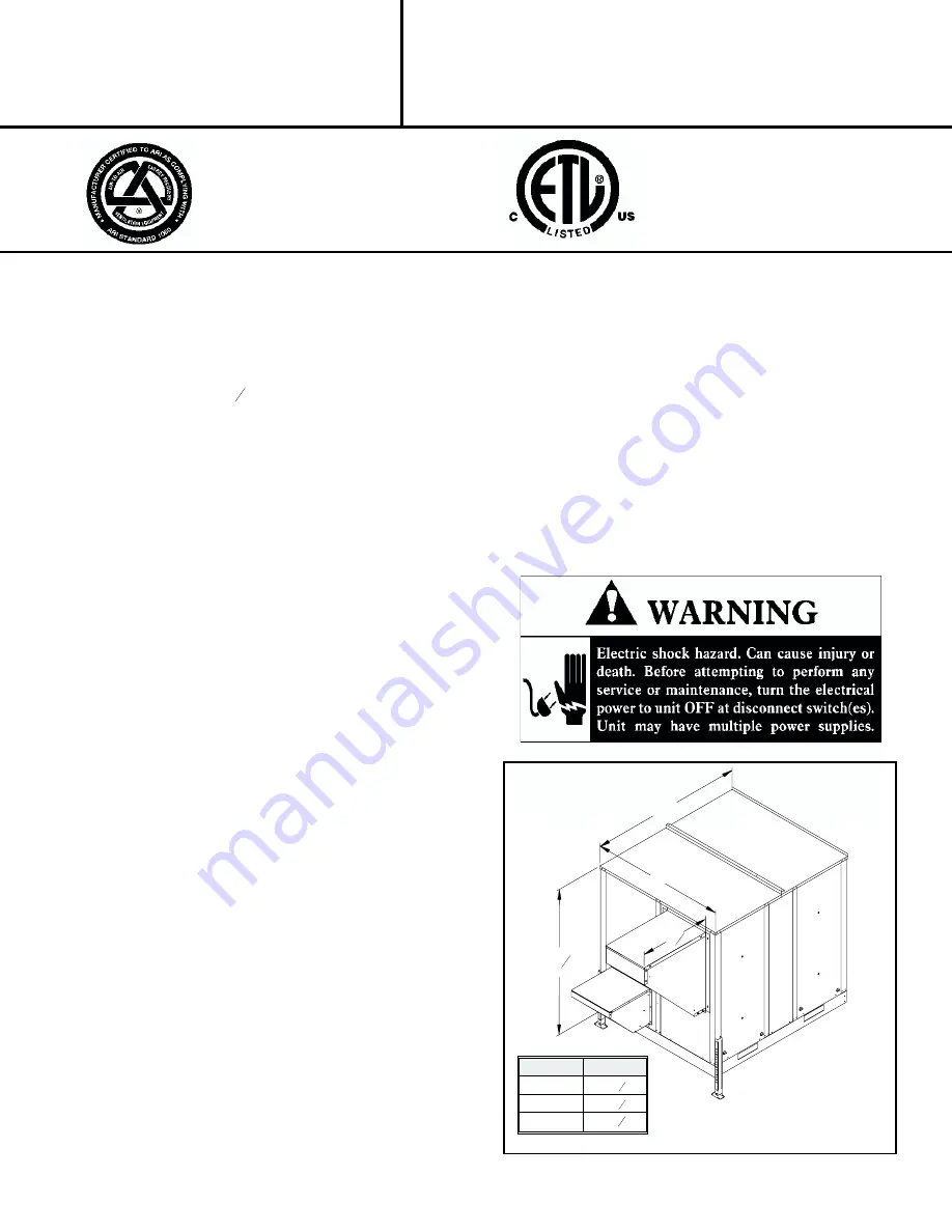
VI -
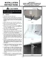
Rigging Unit For Lifting
1- Maximum weight of unit is —- 1500 Lbs. (Crated)
2- Remove crating. Then remove access panel to retrieve
bag assembly. Replace access panel.
3- All panels must be in place for rigging.
4- Lifting lugs are supplied with the unit. Loosen machine
bolts and rotate lifting lug.
Energy recovery COMPONENT certified
to the ARI Air-to-Air Energy Recovery
Ventilation Equipment Certification
Program in accordance with ARI
Standard 1060-2000 . Actual performance
in packaged equipment may vary.
ETL Certified per UL 1995
and CSA 22.2
INSTALLATION
INSTRUCTIONS
MAXA-MI$ER™
UNITARY ENERGY RECOVERY VENTILATOR
MODEL VR036A15H/25H & VR046A15H/25H
& VR062A15M/H/25M/H (STATIONARY)
035-19269-000-A-0203
60
57
3
8
A
30
1
2
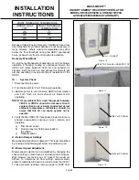
MODEL#
A
VR036
46
5
8
VR046
52
5
8
VR062
58
7
8
Summary of Contents for MAXA-MISER VR036A15H
Page 10: ...PAGE 10 ...


