background image

Form Number:  160.79-O3 (921)

                                                  Supersedes: 160.79-O3 (1020)

Operations Manual                                                       
Issue Date:  2021-09-16                                                

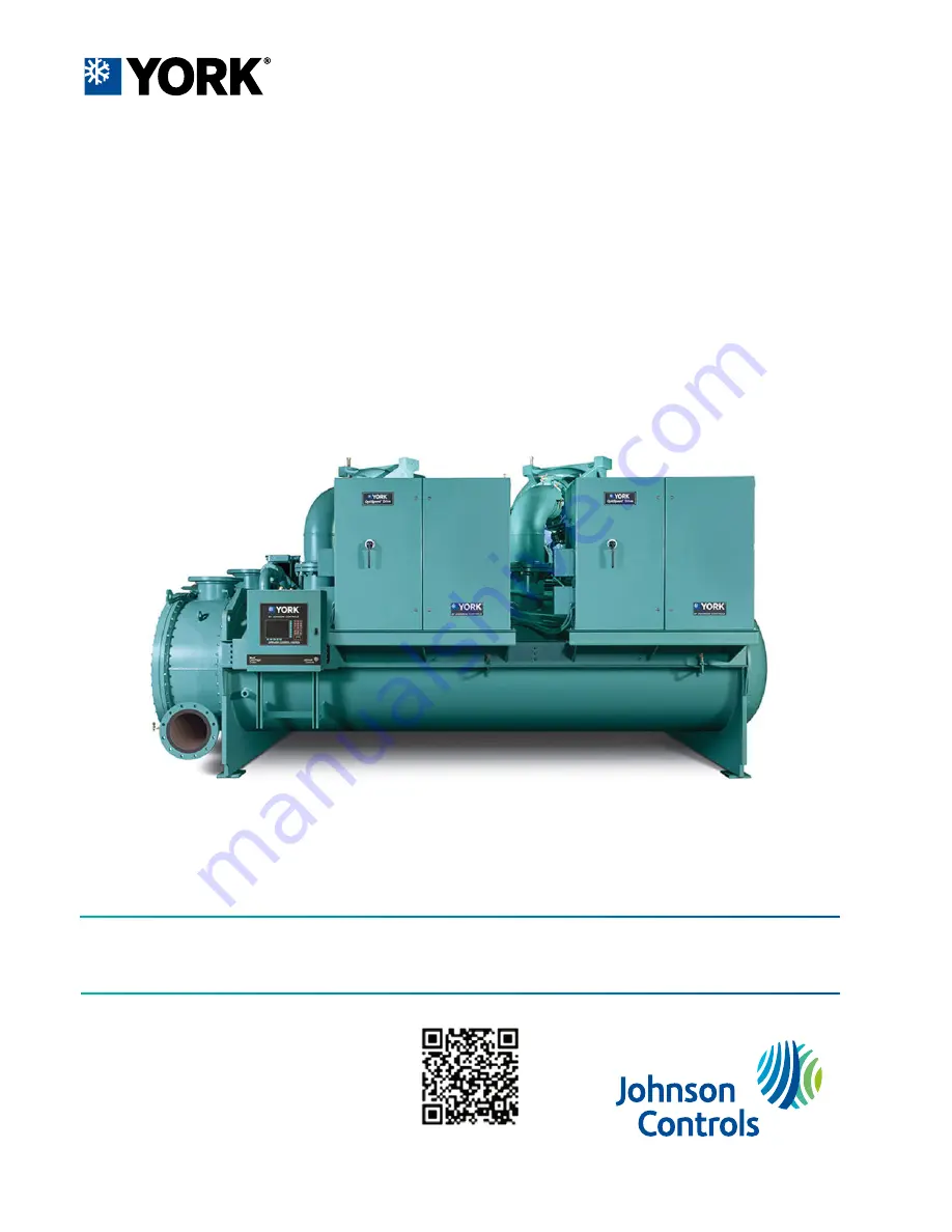
Model YD Mod D with OptiView Control

Center

Centrifugal Liquid Chillers

Summary of Contents for YD Mod D

Page 1: ...Form Number 160 79 O3 921 Supersedes 160 79 O3 1020 Operations Manual Issue Date 2021 09 16 Model YD Mod D with OptiView Control Center Centrifugal Liquid Chillers...

Page 2: ...2 Model YD Mod D with OptiView Control Center...

Page 3: ...2 Proximity probe calibration screen 44 Pre rotation vanes calibration screen 46 Variable Geometry Diffuser VGD screen 47 Variable Geometry Diffuser VGD setpoints screen 49 Variable Geometry Diffuser...

Page 4: ...114 Security log details screen 115 Custom view screen 116 Custom view setup 117 Trend screen 118 Trend setup screen 120 Advanced trend setup screen 122 Common slots screen 124 Slot numbers 125 Displ...

Page 5: ...It is expected that these individuals possess independent training that will enable them to perform their assigned tasks properly and safely It is essential that prior to performing any task on this...

Page 6: ...cs johnsoncontrols com chillers It is the responsibility of rigging lifting and operating service personnel to verify the applicability of these documents to the equipment If there is any question reg...

Page 7: ...enewal Parts YD Mod D hvacnavigator com Unit Renewal Parts YD Mod D hvacnavigator com K1 K2 K3 K4 and K7 Compressor Part Guide 160 75 RP2 Conditioned based maintenance Traditional chiller maintenance...

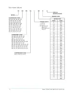
Page 8: ...Nomenclature Model YD Mod D with OptiView Control Center 8...

Page 9: ...e is closed to prevent compressor backspin due to a gas flow from the running compressor An end switch at both the closed and open positions provides indication of full open and full closed positions...

Page 10: ...at twice the Chiller Current Limit up to 100 In this example with the total chiller current limited to 1120 A one running motor would be allowed to operate at its 100 FLA rating of 800 A Compressor s...

Page 11: ...is period the pre rotation vanes are modulated to maintain the Leaving Chilled Liquid Temperature Setpoint In order to determine if the Lead compressor is meeting the load demand during this period th...

Page 12: ...rt condition exists Also the message Warning Head Pressure High Head Lag Start Limit appears on the System Status line of the display during this condition Condenser refrigerant level control lag star...

Page 13: ...Chiller Pulldown In Effect LED that indicated when the Chiller Pulldown Period is in effect has been eliminated from the MOTOR Screen to avoid confusion with the Lead Compressor Pulldown Demand Limit...

Page 14: ...or has not changed If Single Compressor Mode is selected while both compressors are running a soft shutdown is performed on the lag compressor All faults for this inhibited compressor are continued to...

Page 15: ...y enter Coastdown If an operator initiates a Local Stop with the Keypad Rocker Switch or any fault occurs other than those listed immediately above a Fault Shutdown is performed on all running compres...

Page 16: ...Chiller operation flow chart Figure 2 Chiller operation flow chart Model YD Mod D with OptiView Control Center 16...

Page 17: ...Figure 2 Chiller operation flow chart 17 Model YD Mod D with OptiView Control Center...

Page 18: ...Figure 2 Chiller operation flow chart Model YD Mod D with OptiView Control Center 18...

Page 19: ...Figure 2 Chiller operation flow chart 19 Model YD Mod D with OptiView Control Center...

Page 20: ...Figure 2 Chiller operation flow chart Model YD Mod D with OptiView Control Center 20...

Page 21: ...Figure 2 Chiller operation flow chart 21 Model YD Mod D with OptiView Control Center...

Page 22: ...Figure 2 Chiller operation flow chart Model YD Mod D with OptiView Control Center 22...

Page 23: ...in at Service access level or higher The setpoints and parameters displayed on these screens are explained in detail in Service Manual Form 160 69 M1 C These parameters affect chiller operation and mu...

Page 24: ...em screens At the base of the display are 5 additional buttons The area to the right of the keypad is used for data entry with a standard numeric keypad provided for entry of system setpoints and limi...

Page 25: ...t on the screen will then be categorized into three distinct groups Display Only Programmable and Navigation Below is a short description of what types of information are included in these groups The...

Page 26: ...oint is being programmed the following procedure applies 1 Press the appropriate setpoint key A dialog box appears displaying the present value the upper and lower limits of the programmable range and...

Page 27: ...display the upper right soft key will always return the user to the Home Screen Navigating with soft keys is as simple as pressing the key next to the label containing the name of the desired screen...

Page 28: ...iquid temperature 0 0 94 1 F 17 7 34 5 C Leaving condenser liquid temperature 8 0 133 5 F 13 3 56 3 C Return condenser liquid temperature 8 0 133 5 F 13 3 56 3 C Evaporator refrigerant temperature opt...

Page 29: ...it enters the condenser Motor 1 Motor run LED On when the digital output controlling compressor 1 motor starter is on Motor 1 Full Load Amps Displays the percentage of compressor motor Full Load Amps...

Page 30: ...imary operating conditions at the time the key is pressed The History page provides enhanced reporting capability See History screen for further details Message Clear Service When certain safety or cy...

Page 31: ...s a detailed view of all the Capacity Control parameters showing what overrides are in effect and what the active capacity control output states are Motor Provides a detailed view of the motor control...

Page 32: ...pressure differential between the Pump oil pressure transducer output of oil filter for compressor 2 and the Sump oil pressure transducer The displayed value includes offset pressure derived from auto...

Page 33: ...the temperature of the oil in the sump Chiller current limit setpoint Displays the Chiller Current Limit setpoint The Chiller Current Limit setpoint could be from a 0 20 mA 4 20 mA 0 10 VDC or 2 10 V...

Page 34: ...ure Displays the present refrigerant pressure in the evaporator Evaporator saturation temperature Displays the present saturation temperature in the evaporator Evaporator refrigerant temperature Displ...

Page 35: ...VING CHILLED LIQUID LOW TEMPERATURE cycling shutdown This is done by defining an offset below the Leaving Chilled Liquid Temperature setpoint It is programmable over a range of 1 F to 70 F below the s...

Page 36: ...pressure Displays the refrigerant pressure in the condenser Drop leg refrigerant temperature Displays the temperature of the refrigerant in the drop leg between the condenser and evaporator shells if...

Page 37: ...Service When a Drop Leg Refrigerant Sensor has been installed it must be enabled via this toggle before the system will utilize the new enhanced resolution input Table 12 Navigation Button Access leve...

Page 38: ...When the actual level is 48 to 63 the level is shown as 80 full When the actual level is 64 to 79 the level is shown as 90 full Actual levels above 79 are shown as 100 full Note Requires a logon acce...

Page 39: ...he Open or Close buttons Adjustable 0 1 to 10 default 1 0 Open Pressing this button will set the Condenser Level Control Valve Mode to Manual if it had been in Auto and will increase the current Conde...

Page 40: ...differential between the Pump Oil Pressure transducer for compressor 1 and the common Sump oil pressure transducer If either of these transducers are out of range the display field will show XX X PSID...

Page 41: ...cess level Displays a subscreen that allows calibration of the proximity probe and pre rotational vanes and viewing of parameters for compressor 2 Also manual control of the discharge valve and pre ro...

Page 42: ...10 seconds into the system pre lube period During this time the transducers are sensing the same pressure and their outputs should indicate the same pressure As a result due to accuracy tolerances in...

Page 43: ...tatus of the compressor Discharge Valve as closing closed opening or opened High pressure switch Indicates the status of the compressor High Pressure Switch open or closed Programmable Software does n...

Page 44: ...he sump oil pressure transducer If either of the transducers used to calculate this differential is out of range the display field will show XX X Calibration in progress LED Indicates that the calibra...

Page 45: ...Table 23 Navigation Button Access level Description Home View Returns to the Home screen Compressor View Returns to the Compressor screen 45 Model YD Mod D with OptiView Control Center...

Page 46: ...ts success or failure PRV feedback voltage Displays the pre rotation vanes position potentiometer feedback voltage Vane motor switch LED Lights when the vane motor switch is closed Table 25 Programmab...

Page 47: ...ector Voltage Limit Set in the VGD Setpoints Screen with Service Level Access Low limit Displays the Low Stall Detector Voltage Limit Set in the VGD Setpoints Screen with Service Level Access Mach num...

Page 48: ...reading Condenser pressure Displays the Condenser Pressure Transducer value Head pressure Displays the Head Pressure value condenser pressure evaporator pressure evaporator pressure Table 28 Programma...

Page 49: ...re is performed by Service Technician Variable Geometry Diffuser 1 VGD opening LED Lights when an open signal is being applied to the VGD Variable Geometry Diffuser 1 VGD closing LED Lights when a clo...

Page 50: ...Control Status while the override is in effect Extreme stall duration Service 10 to 20 minutes default 10 This setpoint applies to both VGD controls This setpoint specifies the maximum allowed time an...

Page 51: ...level Description Home Service Returns to the Home screen VGD 1 Service Returns to the Variable Geometry Diffuser 1 Screen VGD 2 Service Returns to the Variable Geometry Diffuser 2 Screen 51 Model YD...

Page 52: ...ights when a calibration sequence is in progress Calibration messages Displays text messages which step the user through the calibration process and indicate its success or failure Table 34 Programmab...

Page 53: ...shown as full open Lead PRV position Displays the position of the Lead Compressor Pre Rotation Vanes over the range of 0 closed to 100 fully open Displayed at XXX until calibration procedure is perfo...

Page 54: ...eriod Displays the period of time after no more surges are detected that the Hot Gas Valve will begin to close programmable 30 minutes to 120 minutes default 30 minutes Minimum load Enables or disable...

Page 55: ...olling count of the total single compressor surge events that have occurred within the last number of minutes displayed as the SURGE WINDOW TIME This value is reset when one or both compressors have s...

Page 56: ...lays the total number of dual compressor surge events detected over the lifetime of the chiller Surge detected LED Lights for 5 seconds each time a dual compressor surge is detected Lead compressor Id...

Page 57: ...r of surge events in the most recent minute is added thus providing a rolling count of the total surge events that have occurred in the last COUNT WINDOW minutes This value is reset when the chiller s...

Page 58: ...ents SURGE WINDOW COUNT are compared to the maximum allowed COUNT LIMIT for the purpose of detecting an excess surge situation Count limit Operator Allows the user to define the maximum number of surg...

Page 59: ...Table 44 Navigation Button Access level Description Home View Returns to the Home screen Surge View Returns to the Main Surge screen 59 Model YD Mod D with OptiView Control Center...

Page 60: ...tdown Surge window count Displays the number of dual compressor surge events that have occurred in the last 15 to 120 minutes as programmed with the COUNT WINDOW setpoint If the lag compressor has bee...

Page 61: ...the Surge Window Count exceeds the Count Limit the lag compressor is taken off line and Warning Anti Surge Surge Limit Exceeded is displayed This is displayed until manually reset with the Warning Re...

Page 62: ...Input Current Limit and Pulldown Current Limit or BAS ISN current limit Entering liquid evaporator Displays the temperature of the chilled liquid as it enters the evaporator Entering liquid condenser...

Page 63: ...ed VGD Variable Geometry Diffuser or HGBP Hot Gas Bypass Valve if installed Active Output LED Indicates which device is currently selected by the control for manipulation Command Displays the output c...

Page 64: ...the Capacity Cycling screen where the Operator can set the Compressor staging and lockout Compressor Displays the Compressor screen Setpoints Displays the Capacity Control Setpoints screen Hot gas Dis...

Page 65: ...rammed LCHLT setpoint When the compressor motor starts the Active LCHLT Setpoint is ramped from this value to the programmed LCHLT Setpoint at the programmable LCHLT Setpoint Ramp Rate default 0 1 F s...

Page 66: ...evel Description Home Service Returns to the Home screen Capacity control Service Returns to the Capacity Control screen Anti surge tuning Service Navigates to the Anti Surge Tuning screen Model YD Mo...

Page 67: ...ing in troubleshooting Programmable There are no Programmable setpoints on this screen The technician may be asked to provide a picture of this screen by Product Technical Support or Chiller Engineeri...

Page 68: ...e previous reading is subtracted from the present reading and the last 5 results are averaged to obtain a five point rolling average Displayed as zero when chiller is not running Lead Full Load Amps D...

Page 69: ...Chiller Steady State Period If the requirement is not being met the lag compressor is started After the Chiller Pulldown Period has ended the Chiller Steady State Period begins and is in effect until...

Page 70: ...down Period is no longer in effect and until the Temperature Differential exceeds the Maximum Delta T Setpoint at which time Waiting Maximum Delta T Time is displayed or the Chiller Current Limit is s...

Page 71: ...ingle Mode The operation is restricted to one compressor only When starting the chiller in Single Compressor mode the operator does not designate which compressor will run Rather the Lead compressor i...

Page 72: ...d the common Sump oil pressure LOP transducer If this compressor is the lead compressor includes offset pressure derived from auto zeroing during the compressor 1 pre lube However if compressor 2 is t...

Page 73: ...ing to During the pre lube and for the first 15 seconds of System Run this is the Target Setpoint and is fixed at 45 0 psid For the remainder of compressor 2 run it is the programmed Setpoint Oil Pres...

Page 74: ...culate this differential is out of range the display field will show XX X Pump oil pressure HOP Displays the high side oil pressure measured at the compressor bearing input Oil pump drive command freq...

Page 75: ...he increment or decrement speed commands to the compressor Variable Speed Oil Pump Presently it is set to 0 9 seconds and cannot be changed Variable speed oil pump speed control Raise Service With the...

Page 76: ...compressor 1 and compressor 2 have run Number of starts Individually indicates the total number of times compressor 1 and compressor 2 have started Motor heater LED Indicates whether the digital outp...

Page 77: ...eturns to the Home screen VSD 1 View Displays the subscreen which provides more information about Variable Speed Drive 1 VSD 2 View Displays the subscreen which provides more information about Variabl...

Page 78: ...med value PRV position Displays the Pre rotation Vane position as a value between 0 and 100 Pulldown demand time left Displays the time remaining in the programmed pulldown period if the value is nonz...

Page 79: ...ys the subscreen which provides more information about the variable speed drive Filter details harmonic filter installed only View Displays the subscreen which provides more information about the Harm...

Page 80: ...time remaining in the programmed pulldown period if the value is nonzero Output voltage Displays the output voltage measured to the motor Output frequency Displays the present output frequency to the...

Page 81: ...ncy Rating 60 Hz or 50 Hz Full Load Amps Displays the maximum amps at which the motor can operate VSD cooling fans output LED Lights when the digital output from the MVVSD control has set the Cooling...

Page 82: ...ation warning or safety that is in effect and resets the Operating Hours Since Last Lubrication to zero Table 71 Display only fields Field LED name Description Date of last motor lubrication warning o...

Page 83: ...entry or to place a blank space scroll to the beginning of the alphabet The selection prior to the letter A is a blank space Use the key to enter a period decimal point During the entry process if it...

Page 84: ...value Pulldown demand time left Displays the time remaining in the programmed pulldown period if the value is nonzero Full load amps Displays the Full Load Amps value as reported by the VSD VSD model...

Page 85: ...Table 75 Navigation Button Access level Description Home View Returns to the Home screen VSD View Returns to the VSD screen 85 Model YD Mod D with OptiView Control Center...

Page 86: ...s operating or not Phase rotation Displays the phase rotation detected by the Harmonic Filter A B C or C B A DC bus voltage Displays the DC Bus voltage as measured by the Harmonic Filter Total supply...

Page 87: ...Programmable None Table 77 Navigation Button Access level Description Home View Returns to the Home screen VSD View Returns to the VSD screen 87 Model YD Mod D with OptiView Control Center...

Page 88: ...tor This value is provided by the VSD Logic Board PRV position Displays the present Pre rotation Vanes position as a value between 0 closed and 100 full open Motor windings Temperature Displays the en...

Page 89: ...heading text and data boxes do not appear Motor bearings Vibration Displays the Shaft End and Opposite End vibration values The vibration values are not in any particular units of measure They are re...

Page 90: ...ated to achieve equal current to both motors The Chiller Full Load Amps FLA is the total of compressor 1 motor and compressor 2 motor FLA ratings with each motor having an equal FLA rating For example...

Page 91: ...Limit Setpoint is set at 70 the Chiller Current is limited to 1120 A If only one motor is running the Motor Current Limit see Motor Current Limit Setpoint above for that motor would be set to 100 and...

Page 92: ...ng system is installed on Motor 1 Motor 2 details View Displays the motor temperatures and vibration readings if the optional Motor Monitoring system is installed on Motor 2 Motor lubrication View Mov...

Page 93: ...cling Shutdown Offset from the Leaving Chilled Liquid Temperature Setpoint If this value is below the absolute minimum allowed shutdown temperature the minimum value is displayed Leaving chilled liqui...

Page 94: ...he setpoint to a minimum cutout of 36 F water or 6 F brine It establishes the minimum allowed temperature for the Leaving Chilled Liquid Temperature and prevents overcooling of the building When the L...

Page 95: ...5 Navigation Button Access level Description Home View Returns to the Home screen Setup View Displays the subscreen allowing setup of general system parameters 95 Model YD Mod D with OptiView Control...

Page 96: ...On R134a Liquid type Service Displays Water or Brine as set by position of SW1 2 Off Water Chilled liquid pump operation Service Displays as Standard or Enhanced Anti recycle Service Selectable as Di...

Page 97: ...is setpoint will affect the display of the time on the chiller panel and on all reports generated 12 hour time format will include the AM and PM modifiers and show the range of time between 1 00 and 1...

Page 98: ...up to 6 weeks in advance At the end of each week the schedule for the next week is created by combining the standard week definition and the next defined exception week The schedule is then updated a...

Page 99: ...gramming for exception days within the next 6 weeks Repeat Sunday Operator Duplicates the schedule defined for Sunday for the remainder of the standard weekdays Print View Generates a Schedule print r...

Page 100: ...r Custom Password values Each Password will then require a corresponding User ID and User Level Service Technicians refer to Service Manual Form 160 79 M1 Custom user access level 4 Service This allow...

Page 101: ...Table 91 Navigation Button Access level Description Home View Returns to the Home screen Setup View Returns to the Setup screen 101 Model YD Mod D with OptiView Control Center...

Page 102: ...setup Access level required Operator Pressing this key places a green selection box around the first changeable parameter Use the and keys to place the selection box around the desired parameter to be...

Page 103: ...time Operator Set the time at which scheduled print logs will begin Output interval Operator Define the interval at which log printing will occur between 1 and 1440 minutes Printer type Operator Defin...

Page 104: ...ned serial number for the micropanel Chiller serial number Factory defined serial number for the chiller system Condenser and evaporator design load information Factory defined description of the cond...

Page 105: ...umber of starts Admin to change Displays the total number of the starts the chiller has initiated Chiller operating hours Admin to change Displays the total accumulated run time of the chiller Edit ph...

Page 106: ...ed thermal flow sensors to sense the evaporator and condenser water flow The paddle type flow sensors when closed apply 115 VAC to I O Board digital inputs on terminal TB4 12 evaporator and TB4 11 con...

Page 107: ...ier Version of the rectifier software VSD Inverter Version of the inverter software VSD Modbus Version of the Modbus communications protocol used to communicate with the VSD Motor Monitoring Version o...

Page 108: ...ry in the microboard Home Returns to the Home screen Setup Navigates to the Setup screen Analog I O Navigates to the Analog I O screen Digital I O Navigates to the Digital I O screen Comms Navigates t...

Page 109: ...enance was performed Table 108 Programmable Button Access level Description Condenser Small Temperature Difference Warning Threshold Service level and above Displays the condenser small temperature di...

Page 110: ...ge button and enter code 0726 Condenser High Small Temp Difference Warning Test Op Use this to enable or disable the Condenser High Small Temperature Difference feature A service warning appears as ye...

Page 111: ...last normal shutdown A normal shutdown is defined as Local Start Key on Home screen Remote Digital Analog or ISN Last fault while running This window displays the date and time and the description of...

Page 112: ...me of the associated shutdown Trending View Displays a subscreen allowing the user to view trending data on selected chiller parameters Custom view View Displays a subscreen allowing the user to view...

Page 113: ...e Description History printout This is the on screen printout of the system parameters Table 114 Programmable Button Access level Description Page up View Scroll up in the displayed data if applicable...

Page 114: ...Displays the category of the setpoint such as the motor evaporator and condenser Setpoint Displays the setpoint that was changed New value Displays the new value of the setpoint Table 117 Programmabl...

Page 115: ...ays the setpoint category that was changed Time Displays the time the setpoint was changed Date Displays the date the setpoint was changed Access level Displays the login access level used to make the...

Page 116: ...vice call the display can be cleared or the parameters can be left there for monitoring by operations personnel Programmable None Table 122 Programmable Button Access level Description Print View This...

Page 117: ...er to zero clears the display of this slot number Select Service First use the Page Up and Page Down keys to scroll through the Slot Numbers list and note the number of the parameters to be displayed...

Page 118: ...e value will be plotted at the minimum value Similarly if the actual value is greater than the Y Axis label maximum for that parameter the value will be plotted at the maximum value There are three ty...

Page 119: ...View Allows the data on the trend screen to be printed in tabular format If set to EXISTING a snapshot of the data presently on the screen is sent to the printer If set to NEW all data collected afte...

Page 120: ...box is displayed permitting data entry Chart type Operator Selects continuous one screen or triggered type of graph Collection interval Operator Selects the interval at which the parameters are sample...

Page 121: ...AX MUST BE TREND MIN If the parameter selected for this data point is a digital type on off this value must be set to zero 0 Zero indicates the OFF state Data point max 1 6 Operator Only displayed if...

Page 122: ...ay per the selected Trigger Action A Secondary Trigger can be evaluated with the Primary Trigger to start stop data collection The Primary to Secondary Operator is used to define the trigger combinati...

Page 123: ...ay timer has elapsed If the Trigger Action is set to Stop data collection will stop after the triggers evaluate as true and the delay timer has elapsed Primary to secondary operator Operator Selects w...

Page 124: ...ugh 6 Note Requires a login access level of OPERATOR or higher Table 133 Display only fields Field LED name Description Slot numbers Slot numbers of the most commonly used parameters Table 134 Program...

Page 125: ...Refrigerant level control 8324 Condenser Active Level Setpoint 8206 Condenser Refrigerant Level 18376 Condenser Level Control State 8325 Condenser Level Control Valve Command 2072 Subcooler Effectiven...

Page 126: ...306 Full Load Amps Motor 2 18708 Motor Run 18709 Full Load Amps 2351 Operating Hours Since Last Motor Lubrication Variable geometry diffuser 8287 Stall Detector Board 1 output voltage 8302 Stall DC Pr...

Page 127: ...2 DC Bus Voltage AU 18850 VSD 2 DC Bus Voltage AL 18851 VSD 2 DC Bus Voltage BU 18852 VSD 2 DC Bus Voltage BL 18853 VSD 2 DC Bus Voltage CU 18854 VSD 2 DC Bus Voltage CL 18771 VSD 2 Phase A Heatsink T...

Page 128: ...rge Frequency 18241 Lag Surge Frequency 17681 Active Anti Surge Minimum Frequency 17682 Lead Active Minimum PRV Position 17777 Evaporator Pressure Override Threshold 17776 Condenser Pressure Override...

Page 129: ...hutdown of the entire chiller A soft shutdown is performed on the running compressors for the following shutdowns Leaving Chilled Liquid Temperature Low Temperature Remote Stop ISN Analog Remote or Di...

Page 130: ...the pre rotation vanes are inhibited from further opening This prevents a further current rise If the current continues to rise to the start close threshold the Vanes begin closing until the current...

Page 131: ...ble speed drive oil pump is 45 Hz This inhibit is released when the compressor 1 motor current decreases to 15 FLA and the Clear Fault button is pressed on the Home screen A complete 150 second coastd...

Page 132: ...both compressors are driven to the full open position 100 and held there until this warning is manually is cleared When cleared the VGD of both compressors return to normal operation Warning Condition...

Page 133: ...lue during the remaining 90 seconds of the cycle for compressor 1 This message must be manually cleared using the Warning Reset key in Service access level or higher As soon as the message is cleared...

Page 134: ...the setpoint Warning Evaporator Low Pressure Limit The evaporator pressure has decreased to the warning threshold This threshold is fixed in water cooling applications In brine cooling applications t...

Page 135: ...econd this message is displayed This check is only performed if the lead compressor has been running for 5 or more seconds the evaporator pressure transducer is sensing a pressure that is in range 6 7...

Page 136: ...or cycling screen this fault does not cause compressor 2 to shutdown or prevent it from starting When this fault occurs on a locked out compressor it is displayed as a warning This allows the user to...

Page 137: ...tor 2 A power fault condition occurs when the motor current drops below 10 FLA This protects against potential compressor damage due to rapid opening and reclosure of the motor starter When it detects...

Page 138: ...seconds of receiving the close command If the chiller was running when this occurred the pre rotation vanes of the running compressors are driven fully closed prior to shutting down the chiller The ch...

Page 139: ...a cycling shutdown when displayed in orange characters safety shutdown when displayed in red characters The control center is configured for auto restart or manual restart after power failure by a qua...

Page 140: ...temp Smart freeze is activated only if the feature has been enabled by a service technician and the Leaving Chilled Liquid Temperature setpoint is 38 0 F Evaporator Transducer Or Leaving Liquid Probe...

Page 141: ...lt does not cause compressor 1 to shutdown or prevent it from starting When this fault occurs on a locked out compressor it is displayed as a warning This allows the user to know that a fault exists o...

Page 142: ...essor Cycling Screen this fault does not cause compressor 2 to shutdown or prevent it from starting When this fault occurs on a locked out compressor it is displayed as a warning This allows the user...

Page 143: ...he warning condition will revert back to a shutdown as soon as the lockout is removed and will cause the chiller to trip OIL PUMP 2 PRESSURE TRANSDUCER OUT OF RANGE The Chiller both compressors has sh...

Page 144: ...Faults button CONTROL PANEL POWER FAILURE A Control Power failure has occurred If the power failure duration was the duration of the applicable Coastdown period 2 5 minutes standard 15 minutes steam...

Page 145: ...must be evaluated by a qualified Service Technician prior to starting the chiller Starting the chiller without this evaluation could result in severe compressor damage To prevent the chiller from sta...

Page 146: ...ration has not been performed The chiller can be started after the calibration and a special reset procedure has been performed WATCHDOG SOFTWARE REBOOT The Microboard s software Watchdog initiated a...

Page 147: ...e a report If permanently connected a DATA LOGGING feature can produce a status report automatically beginning at an Operator selected start time and occurring at an Operator selected interval thereaf...

Page 148: ...parameters as follows Table 145 Com port parameters Field Value Bits per second Baud Rate 57600 Data bits 8 Parity None Stop Bits 1 Flow control None If DTR DSR is used set to Hardware If no DTR DSR s...

Page 149: ...Set Ready Pin 7 Request To Send Pin 8 Clear To Send Pin 9 Ring Indicator The connector on the PC has male pins therefore the mating cable needs to terminate DB9 F female pin connector Figure 55 Commu...

Page 150: ...Figure 57 Sample printout status Model YD Mod D with OptiView Control Center 150...

Page 151: ...Figure 57 Sample printout status 151 Model YD Mod D with OptiView Control Center...

Page 152: ...Figure 58 Sample printout setpoints Model YD Mod D with OptiView Control Center 152...

Page 153: ...Figure 58 Sample printout setpoints 153 Model YD Mod D with OptiView Control Center...

Page 154: ...Figure 59 Sample printout schedule Model YD Mod D with OptiView Control Center 154...

Page 155: ...Figure 60 Sample printout sales order 155 Model YD Mod D with OptiView Control Center...

Page 156: ...Figure 61 Sample printout history Model YD Mod D with OptiView Control Center 156...

Page 157: ...Figure 61 Sample printout history 157 Model YD Mod D with OptiView Control Center...

Page 158: ...Figure 62 Sample printout security log report Figure 63 Sample printout trend data new or existing points Model YD Mod D with OptiView Control Center 158...

Page 159: ...Figure 64 Sample printout custom screen report 159 Model YD Mod D with OptiView Control Center...

Page 160: ...ters mm Weight Pounds lb 0 4536 Kilograms kg Velocity Feet Second fps 0 3048 Meters Second m s Feet of Water ft 2 989 Kilopascals kPa Pressure drop Pounds Square Inch psi 6 895 Kilopascals kPa Tempera...

Reviews: