background image

OPERATING & MAINTENANCE

MILLENNIUM

®

CENTRIFUGAL LIQUID CHILLERS

Supersedes: 160.55-O1 (604)

Form 160.55-O1 (920)

MODEL YT (STYLE J)

R-123 COOLING ONLY

WITH OPTIVIEW

 CONTROL CENTER

FOR ELECTRO-MECHANICAL STARTER,

SOLID STATE STARTER and VARIABLE SPEED DRIVE

29509A

Issue Date: 

September 18, 2020

Summary of Contents for YT Millennium

Page 1: ...GAL LIQUID CHILLERS Supersedes 160 55 O1 604 Form 160 55 O1 920 MODEL YT STYLE J R 123 COOLING ONLY WITH OPTIVIEW CONTROL CENTER FOR ELECTRO MECHANICAL STARTER SOLID STATE STARTER and VARIABLE SPEED D...

Page 2: ...cument and any referenced materials This in dividual shall also be familiar with and comply with all applicable industry and governmental standards and regulations pertaining to the task in question S...

Page 3: ...DIAGRAM UNIT WITH ELECTRO MECHANICAL STARTER 160 55 PW1 WIRING DIAGRAM UNIT WITH SOLID STATE STARTER MOD B 160 55 PW2 WIRING DIAGRAM UNIT WITH VARIABLE SPEED DRIVE 160 55 PW3 RENEWAL PARTS UNIT 160 4...

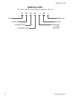
Page 4: ...ORM 160 55 O1 920 NOMENCLATURE The model number denotes the following characteristics of the unit YT K3 C4 E2 CR J Model Design Level Cooler Code Motor Code Condenser Code Power Supply for 60 Hz Compr...

Page 5: ...Control Center 9 SECTION 3 Printers 112 SECTION 4 System Operating Procedures 124 SECTION 5 System Components Description 131 SECTION 6 Operational Maintenance 135 SECTION 7 Troubleshooting 138 SECTIO...

Page 6: ...CREEN 68 FIG 30 PRINTER SCREEN 70 FIG 31 SALES ORDER SCREEN 72 FIG 32 OPERATIONS SCREEN 74 FIG 33 HISTORY SCREEN 76 FIG 34 HISTORY DETAILS SCREEN 78 FIG 35 SECURITY LOG SCREEN 79 FIG 36 SECURITY LOG D...

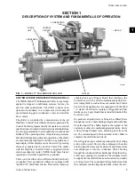
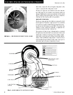
Page 7: ...from the condenser into the liquid return line where the vari SECTION 1 DESCRIPTION OF SYSTEM AND FUNDAMENTALS OF OPERATION 29509A CONDENSER CONTROL CENTER COMPRESSOR MOTOR COOLER FIG 1 MODEL YT MILLE...

Page 8: ...ation CAPACITY CONTROL The major components of a chiller are selected for full load capacities therefore capacity must be controlled to maintain a constant chilled liquid temperature leav ing the cool...

Page 9: ...oints and manual control shown in this book that are for Service Technician use only They are only displayed when logged in at SERVICE access level or higher These parameters affect chiller operation...

Page 10: ...the respective revision level increments C Commercial chiller MLM Used on Microboard 031 01730 000 OPT Used on Microboard 031 02430 000 02 YT chiller xx controls revision level 00 01 etc y language p...

Page 11: ...FORM 160 55 O1 920 11 YORK INTERNATIONAL THIS PAGE INTENTIONALLY LEFT BLANK TO MAINTAIN FORMAT...

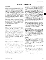
Page 12: ...Center display is highlighted by a full screen graphics display This display is nested within a standard keypad and is surrounded by soft keys which are redefined based on the currently displayed scre...

Page 13: ...gins with an Access Level of VIEW This will allow the user to navi gate to most screens and observe the values displayed there However the user will not be allowed to change any values To change any v...

Page 14: ...ig 24 for an example NAVIGATION In order to maximize the amount of values which the panel can display to the user and in order to place those values in context multiple screens have been designed to d...

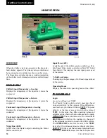
Page 15: ...3 F 7 2 107 9 C Oil Temperature 19 0 226 3 F 7 2 107 9 C Condenser Pressure 2 5 35 3 PSIA 17 2 243 4 KPAA Condenser Temperature R11 1 4 124 2 F 18 5 51 2 C Condenser Temperature R123 7 2 130 1 F 13 7...

Page 16: ...nly if the chiller system is utilizing a Vari able Speed Drive motor controller or Mod B Solid State Starter This displays the total input power used by the system Full Load Amps This displays the per...

Page 17: ...y Control Details screen Message Clear Access Level Required SERVICE When certain safety or cycling conditions have been detected and the chiller has been shutdown the main status display of the chill...

Page 18: ...locally programmed value in local mode Evaporator Pressure Displays the present refrigerant pressure in the evaporator Evaporator Saturation Temperature Displays the present saturation temperature in...

Page 19: ...his value could come from a 0 20mAor 4 20mA 0 10VDC or 2 10VDC input in Analog Remote mode PWM signal in Digital Remote mode MicroGateway interface in ISN mode or a locally programmed value PROGRAMMAB...

Page 20: ...e evaporator Evaporator Refrigerant Temperature Displays the temperature of the refrigerant in the evapo rator if the sensor is present Small Temperature Difference Displays the difference between the...

Page 21: ...e by defining an offset below the Leaving Chilled Liquid Temperature setpoint It is programmable over a range of 1 F to 64 F below the setpoint to a minimum cutout of 36 F water 34 F water with Smart...

Page 22: ...e The Condenser Refrigerant temperature will be represented by the Condenser Saturation tem perature Drop Leg Refrigerant Temperature Displays the temperature of the refrigerant in the drop leg betwee...

Page 23: ...CE This value allows the user to define the condenser pres sure at which the chiller will initiate a warning Drop Leg Enabled Disabled Access Level Required SERVICE When a Drop Leg Refrigerant Sensor...

Page 24: ...ized at 34 7 PSIA and de energized when the pressure decreases to 29 7 PSIA Top Float Switch LED Illuminated when the Top Float Switch is closed indicating the Purge Tank oil level is less than full E...

Page 25: ...60 minute purge count bypass PROGRAMMABLE High Efficiency Purge System Enabled Disabled Access Level Required SERVICE Selects the appropriate control and purge exhaust thresholds for the installed pu...

Page 26: ...ual level is 0 to 15 the level is shown about 50 full When the actual level is 16 to 31 the level is shown about 60 full When the actual level is 32 to 47 the level is shown about 70 full When the act...

Page 27: ...and sends a RAISE command to the variable orifice Refrigerant Level Control Lower Manual This key puts the level control into manual mode and sends a LOWER command to the variable orifice Refrigerant...

Page 28: ...ay field will show XX X Oil Sump Temperature Displays the temperature of the oil in the sump Discharge Temperature Displays the temperature of the refrigerant in its gaseous state at discharge of the...

Page 29: ...Auto Access Level Required SERVICE This key returns the vane control to automatic mode NAVIGATION Home Access Level Required VIEW Causes an instant return to the Home Screen Pre Rotation Vane Calibra...

Page 30: ...the Pre Rotation Vanes over the range of 0 closed to 100 fully open Displayed at XXX until calibration procedure is performed by service technician Delta P P A parameter that represents system differ...

Page 31: ...LM 02 01 xxx and earlier On SURGE PROTECTION Screen in later Flash Memory Card versions Access Level Required SERVICE Minimum Load Access Level Required SERVICE Maximum Open Flash Memory Card version...

Page 32: ...oc SURGE PROTECTION SCREEN curred in the last 1 to 5 minutes as programmed with the COUNT WINDOW setpoint If the chiller has been running for less than the COUNTWINDOW minutes it is the number of surg...

Page 33: ...T exceeds the COUNT LIMIT at the completion of this period a safety shutdown is performed and Surge Protection Excess Surge is displayed If the Hot Gas Bypassed control is Enabled the Hot Gas Bypass V...

Page 34: ...WINDOW COUNT exceeds the COUNT LIMIT at the completon of the 10 minute extended run period a safety shutdown is performed and Surge Protection Excess Surge is displayed See Hot Gas Bypass and Variabl...

Page 35: ...FORM 160 55 O1 920 35 YORK INTERNATIONAL THIS PAGE INTENTIONALLY LEFT BLANK TO MAINTAIN FORMAT 2...

Page 36: ...bration in Progress LED Indicates the calibration sequence is in progress Calibration Messages These are text messages which step the user through the calibration process and indicate its success or f...

Page 37: ...FORM 160 55 O1 920 37 YORK INTERNATIONAL THIS PAGE INTENTIONALLY LEFT BLANK TO MAINTAIN FORMAT 2...

Page 38: ...e Leaving Chilled Liquid Temperature and Setpoint Delta P P Displays a value based on the pressure differential between the Evaporator and Condenser pressures Condenser Evaporator Evaporator Pre Rotat...

Page 39: ...control into manual mode and increases the present command frequency by the defined frequency increment It will not raise the value above the maximum allowed frequency Decrease This key puts the VSD f...

Page 40: ...mp Run Output LED Indicates whether the Oil Pump is being commanded to operate Manual Oil Pump Operation Time Left Displays the time remaining in the 10 minute manual oil pump operation described belo...

Page 41: ...non zero PROGRAMMABLE Local Motor Current Limit Access Level Required OPERATOR Allows the user to specify the maximum allowed mo tor current as a percentage of FLA When the motor current reaches this...

Page 42: ...Starter Rating and the maximum allowed Full Load Amps Voltage Phase A B C Display the 3 phase input line voltage values being read from the Solid State Starter Current Phase A B C Display the 3 phase...

Page 43: ...level Supply Voltage Range Access Level Required SERVICE Allows the user to select a specific voltage range for voltage checking When not disabled this line voltage range is used to determine a low li...

Page 44: ...period Input Power Displays the Kilowatts measured by the Solid State Starter kW Hours Displays the cumulative amount of kilowatts used over time Starter Model Displays the Solid State Starter model...

Page 45: ...ic line voltage range for voltage checking When not disabled this line voltage range is used to determine a low line and high line volt age threshold for initiating a shutdown Starting Current Access...

Page 46: ...if the value is non zero Output Voltage Displays the output voltage measured to the motor Output Frequency Displays the present output frequency to the motor Output Current Phase A B C Displays the ph...

Page 47: ...function is used to provide energy savings following chiller start up Pulldown Demand Time Access Level Required OPERATOR Allows the user to set a period of time for which the pulldown demand limit w...

Page 48: ...it value in use This value could come from a 0 20mA 4 20mA 0 10VDC or 2 10VDC input in Analog Remote mode PWM signal in Digital Remote mode MicroGateway interface in ISN mode or a locally programmed v...

Page 49: ...tor current reaches this value the pre rotation vanes will not be permitted to open further If the motor current rises above this value the pre rotation vanes will close to reduce the current to this...

Page 50: ...use This value could come from a 0 20mA 4 20mA 0 10VDC or 2 10VDC input in Analog Remote mode PWM signal in Digital Remote mode MicroGateway interface in ISN mode or a locally programmed value Pulldo...

Page 51: ...age of FLA When the motor current reaches this value the pre rotation vanes will not be permitted to open further If the motor current rises above this value the pre rotation vanes will close to reduc...

Page 52: ...lue Pulldown Demand Time Left Displays the time remaining in the programmed pull down period if the value is non zero VSD Output Frequency Displays the frequency at which the VSD is operating the moto...

Page 53: ...gin at which these adjustments will begin to take place Manual Surge Point This key will force the ACC to map a surge detection at the present operating conditions Mapping a point at these conditions...

Page 54: ...rom a 0 20mA 4 20mA 0 10VDC or 2 10VDC input in Analog Remote mode PWM signal in Digital Remote mode MicroGateway interface in ISN mode or a locally programmed value Pulldown Demand Time Left Displays...

Page 55: ...Local Motor Current Limit Access Level Required OPERATOR Allows the user to specify the maximum allowed mo tor current as a percentage of FLA When the motor current reaches this value the pre rotatio...

Page 56: ...teway interface in ISN mode or a locally programmed value Pulldown Demand Time Left Displays the time remaining in the programmed pull down period if the value is non zero Operating Mode Run Stop Indi...

Page 57: ...the maximum allowed mo tor current as a percentage of FLA When the motor current reaches this value the pre rotation vanes will not be permitted to open further If the motor current rises above this v...

Page 58: ...reatwhich the chiller will restart after it has shut down due to over cooling temperature This value is calculated by adding the Leaving Chilled Liquid Temperature Cycling Offset Restart to the Leavin...

Page 59: ...g Chilled Liquid Temperature Cycling Offset Restart Access Level Required OPERATOR This value allows the user to specify the Leaving Chilled Liquid Temperature at which the chiller will restart after...

Page 60: ...re subscreens for defining general system parameters DISPLAY ONLY 031 01730 000 Microboard Chilled Liquid Pump Operation Displays Standard or Enhanced Motor Type Displays Fixed Speed or Variable Speed...

Page 61: ...ler panel and on all reports generated 12 Hour time format will include the AM and PM modifiers and show the range of time between 1 00 and 12 59 while the 24 Hour time format will show the range of t...

Page 62: ...er Access Level Required VIEW Moves to the subscreen allowing configuration and control of printer functions Sales Order Access Level Required VIEW Moves to the subscreen displaying the Sales Order in...

Page 63: ...FORM 160 55 O1 920 63 YORK INTERNATIONAL THIS PAGE INTENTIONALLY LEFT BLANK TO MAINTAIN FORMAT 2...

Page 64: ...imes which are utilized every week The user may then specify exception Start Stop combinations for any day of the week up to 6 weeks in advance At the end of each week the schedule for the next week i...

Page 65: ...ired OPERATOR Deletes all programming for exception days within the next 6 weeks Select Access Level Required OPERATOR Places a selection box around a start time for a given day Use or cursor arrows t...

Page 66: ...rocess The selected language will not be displayed until after the user navigates from the USER Screen to another Screen English Metric Units Access Level Required OPERATOR Define the unit system Engl...

Page 67: ...FORM 160 55 O1 920 67 YORK INTERNATIONAL 2 THIS PAGE INTENTIONALLY LEFT BLANK TO MAINTAIN FORMAT...

Page 68: ...arameter Use the and keys to place the selection box around the desired parameter to be changed With the selection box around the de sired parameter press the ENTER key A dialog box is displayed permi...

Page 69: ...Stop Bit s Define the number of stop bits at which the panel shall communicate through the modem port NAVIGATION Home Access Level Required VIEW Causes an instant return to the Home Screen Setup Acces...

Page 70: ...vel Required SERVICE Only available if the chiller system utilizes a Variable Speed Drive motor controller The chiller monitors the ACC communications and when a surge point is mapped a short report o...

Page 71: ...FORM 160 55 O1 920 71 YORK INTERNATIONAL NAVIGATION Home Access Level Required VIEW Causes an instant return to the Home Screen Setup Access Level Required VIEW Return to the Setup Screen 2...

Page 72: ...rder number under which the chiller was sold System Information Factory defined conditions for which the chiller was originally rated and sold Condenser and Evaporator Design Load Information Factory...

Page 73: ...FORM 160 55 O1 920 73 YORK INTERNATIONAL THIS PAGE INTENTIONALLY LEFT BLANK TO MAINTAIN FORMAT 2...

Page 74: ...e so arbitrarily Operating Hours Access Level Required ADMIN Displays the total accumulated run time of the chiller This may be reprogrammed to a desired value generally when this value has been reset...

Page 75: ...FORM 160 55 O1 920 75 YORK INTERNATIONAL 2 NAVIGATION Home Access Level Required VIEW Causes an instant return to the Home Screen Setup Access Level Required VIEW Return to the Setup Screen...

Page 76: ...e Digital Analog or ISN Last Fault While Running This window displays the date and time and the de scription of the last safety or cycling shutdown while the system was running Last Ten Faults This wi...

Page 77: ...parameters Custom View Flash memory Card version C MLM 02 01 or later Access Level required VIEW Causes a move to a sub screen allowing the user to view the Custom Setup Screen Security Log Flash Memo...

Page 78: ...ut This is the on screen printout of the system parame ters PROGRAMMABLE Page Up Access Level Required VIEW Scroll up in the displayed data if applicable Page Down Access Level Required VIEW Scroll do...

Page 79: ...plays the setpoint that was changed New Value Displays the value that was entered at the time of the setpoint change PROGRAMMABLE Log Entry Allows the user to select a particular setpoint change for d...

Page 80: ...login access level of SERVICE DISPLAY ONLY Description Displays the setpoint category that was changed Time Displays the time the setpoint was changed Date Displays the date the setpoint was changed...

Page 81: ...urity Log Access Level Required SERVICE Causes an instant return to the Security Log Screen View Details Access Level Required SERVICE Causes a move to a sub screen containing the details of the setpo...

Page 82: ...the sampled parameter is less than theY Axis label minimum for that parameter the value will be plotted at the minimum value Simi larly if the actual value is greater than the Y Axis label maximum fo...

Page 83: ...display all trended data points simul taneously or select a single trended data point for display hiding the other data points Selections are ALL DATA or DATA POINT X 1 6 Print Flash Memory Card versi...

Page 84: ...the DATA COLLECTION INTERVALor the interval at which the parameter is sampled This interval is programmable over the range of 1 second to 3600 seconds 1 hour in one second increments The selected inte...

Page 85: ...parameter selected for this data point is a digital type on off this value must be set to zero 0 Zero indicates the OFF state Data Point Max 1 6 Access Level Required OPERATOR Only displayed if the a...

Page 86: ...ected Trigger delay per the selected Trigger Action ASecondary Trigger can be evaluated with the Primary Trigger to start stop data collection The Primary to Sec ondary Operator is used to define the...

Page 87: ...fter the triggers evaluate as true and the delay timer has elapsed If the Trigger Action is set to Stop data collection will stop after the Triggers evaluate as true and the delay timer has elapsed Pr...

Page 88: ...bers into Data Points 1 through 6 Requires a login access level of OPERATOR or higher DISPLAY ONLY Slot Numbers These are the slot numbers of the most commonly used parameters PROGRAMMABLE Page Down A...

Page 89: ...ing At completion of the service call the display can be cleared or the parameters can be left there for monitor ing by operations personnel DISPLAY ONLY None PROGRAMMABLE Print Access Level Required...

Page 90: ...a green colored selection box around Custom Slot 1 If it is desired to change an already entered parameter use the 5 and 6 keys to place the selection box around the slot number to be changed With th...

Page 91: ...re 1538 Oil Pump Control Mode 1539 Oil Pump Is Pump On 1540 Oil Pump Manual Time Left SLOT NO DESCRIPTION 1792 Leaving Chilled Liquid Temperature 1793 Leaving Chilled Liquid Temperature Differential 1...

Page 92: ...5 LcSss Is Serial Communications OK 2586 LcSss Panel to Sss Comm Errors 2587 LcSss Sss to Panel Comm Errors SLOT NO DESCRIPTION 2816 VSD Motor HP 2817 VSD 100 Full Load Amps 2818 VSD Input Power 2819...

Page 93: ...rmonic Distortion 2891 Filter Maximum Total Demand Distortion 2 SLOT NO DESCRIPTION 8205 Refrigerant Level Is Control Enabled 8206 Refrigerant Level Position 8207 Refrigerant Level Is Valve Closing 82...

Page 94: ...has shut down and the Post run lubrication is being performed On electric motor drive applications the Postlube duration is 150 seconds On Steam Turbine applications it is 15 minutes The actual durat...

Page 95: ...that which was written to the device it is assumed the BRAM and Real time Clock operation is defective and this message is displayed The BRAM should be replaced by a qualified Service Technician This...

Page 96: ...rningwillnotbedisplayedifthePurgeFloatSwitch Error warning below is in ef fect WARNING PURGE FLOATSWITCHERROR With the chiller running the Purge Float Switches were in invalid states Typically this is...

Page 97: ...ommands can be received in Digital Remote mode via I O Board TB4 7 8 or in ISN Integrated Systems Network Remote mode via the MicroGateway serial communications LOCAL STOP A local shutdown command has...

Page 98: ...Fault CM 2 Module Overload None Overload Phase Rotation Loss Solid State Starter High Temp 212 F High Temp start inhibit 110 F Fault Current Trigger Board Out of Lock MOTOR CONTROLLER LOSS OF CURRENT...

Page 99: ...not yet received the cause of the fault from the LCSSS via the serial communications link The LCSSS shuts down the chiller by opening the Motor Controller LCSSS Stop Contacts K1 relay located on the s...

Page 100: ...tage in any phase exceeded the high line voltage threshold continuously for 20 seconds The chiller will automaticallyrestartwhenthevoltageinallphasesreturns to the restart level The thresholds are as...

Page 101: ...al Communications fault If communications between the VSD Logic Board Harmonic Filter Logic Board ACC Board and Con trol Center Microboard does not take place during initialization this message will b...

Page 102: ...line Plugged Heat exchanger In cases where the strainer plugs frequently the heat exchanger may eventually plug or become restricted to the point of reduced flow At this point we suggest you back VSD...

Page 103: ...will cause the chiller to shutdown and display this message In most cases the problem will be an open thermistor or broken wir ing to the thermistor The normal thermistor resistance is 10K ohms at 77...

Page 104: ...If this limit is exceeded a shutdown is performed and this message is generated The Filter current is monitored using two DCCT s and these signals are processed by the filter logic board The preset l...

Page 105: ...the chilled liquid to freeze is based on how far the evaporator refrigerant tempera ture is below the freeze threshold as follows Number of seconds to freezing 4053 7 freeze threshold evaporator refri...

Page 106: ...r Temperature Sensor RT7 or Evapo rator Saturation Temperature is indicating a tem perature of 32 0 F Flash Memory Card version C MLM 02 02 xxx and later The chiller can be started after the temperatu...

Page 107: ...et O position This message can indicate a Cycling auto restart after power failure or Safety manual restart after power failure shutdown depend ing upon Control Center configuration It indicates a Cyc...

Page 108: ...lled Rectifier SCR in phase A B or C designated as X in the message has been detected by the Liquid Cooled Solid State Starter Logic Trigger Board The voltage across each SCR in monitored to detect th...

Page 109: ...the primary of the heat exchanger for clogs and silt The chiller can be started after the fault condition clears the RESET button on the VSD Logic Board is pressed and the COMPRESSOR switch is placed...

Page 110: ...and the COMPRESSOR switch is placed in the Stop reset O position HARMONIC FILTER HIGH BASEPLATE TEMPERATURE Applicable to VSD with part number 371 02767 XXX 60 Hz and 371 03700 XXX 50 Hz Requires Fla...

Page 111: ...FORM 160 55 O1 920 111 YORK INTERNATIONAL THIS PAGE INTENTIONALLY LEFT BLANK TO MAINTAIN FORMAT 2...

Page 112: ...YORK INTERNATIONAL 112 FORM 160 55 O1 920 SECTION 3 PRINTERS FIG 43 PRINTERS 23887A OKIDATA MICROLINE 184 23889A WEIGH TRONIX SEIKO DPU 414 00085VIP Printers...

Page 113: ...are similar but print parameters applicable to those devices Figure 44 Status Figure 45 Setpoints Figure 46 Schedule Figure 47 Sales Order Figure 48 History Figure49 SecurityLog FlashMemoryCardver sio...

Page 114: ...hield Hardware required Cable 18 AWG stranded 50ft maximum length Connectors Microboard None Strip 1 4 insulation from wire and insert into screw terminal block Printers Okidata 25 pin plug DB 25P or...

Page 115: ...number to the chiller This number will appear at the top of each report Printer Setup Access Level Required OPERATOR or Higher Using the COMMS Screen the Control Center must be configured to transmit...

Page 116: ...If Drop Leg Sensor enabled Compressor Discharge Temperature 121 6 F Vent Line Solenoid On Oil Sump Oil Pump Run Output On Oil Pressure 30 7 Psid Oil Sump Temperature 137 9 F Skip the following section...

Page 117: ...perature 88 F Converter Heatsink Temperature 102 F Phase A Heatsink Temperature 93 F Phase B Heatsink Temperature 99 F Phase C Heatsink Temperature 97 F Skip the following section if Motor Type is not...

Page 118: ...orator Printers Leaving Chilled Local Setpoint 45 0 F Leaving Chilled ISN Setpoint 45 0 F Leaving Chilled Modem Setpoint 45 0 F Leaving Chilled Analog Setpoint 45 0 F Leaving Chilled Digital Setpoint...

Page 119: ...ge Range Disabled Full Load Amps 215 A Starting Current 1460 A Open SCR Disabled Skip the following section if Motor Type is not VSD Variable Speed Drive Local Motor Current Limit 100 Remote ISN Curre...

Page 120: ...0 00010 Pressure Drop 21 1 Nozzle Arrangement In 2 Nozzle Arrangement Out 3 Leaving Temperature 44 0 Return Temperature 56 0 GPM 1500 0 Tubes 181 Design Load condenser Passes 2 Design Working Pressure...

Page 121: ...ensor enabled Compressor Discharge Temperature 121 6 F Vent Line Solenoid Off Oil Sump Oil Pump Run Output Off Oil Pressure 0 0 Psid Oil Sump Temperature 137 9 F Skip the following section if Hot Gas...

Page 122: ...r Pump Output Off KW Hours 14528 KWH Input Power 150 KW Output Frequency 0 Hz Output Voltage 800 V DC Bus Voltage 600 V DC Inverter Link Current 300 A Phase A Output Current 0 A Phase B Output Current...

Page 123: ...d Active Setpoint 45 0 F Leaving Chilled Liquid Temperature 50 0 F Return Chilled Liquid Temperature 59 3 F Leaving Condenser Liquid Temperature 85 0 F Return Condenser Liquid Temperature 94 9 F Evapo...

Page 124: ...trolled and remains energized as long as the fused disconnect switch to the starter or Variable Speed Drive is energized CHECKING THE OIL LEVEL IN THE OIL RESERVOIR Proper operating oil level the midd...

Page 125: ...vanes and also decreases the speed of the motor if equipped with a Variable Speed Drive to decrease chiller capacity When the chilled liquid temperature rises the actuator will open the prerotation v...

Page 126: ...EN VENT SOLENOID CHECK OIL PRESS 150 SEC 2 5 MIN SYSTEM SHUTDOWN DISPLAY MESSAGE SYSTEM RUN SYSTEM PRELUBE OIL PUMP PRE RUN SYSTEM COASTDOWN OIL PUMP POST RUN 0 25 30 330 1800 0 4 0 5 5 5 30 START TIM...

Page 127: ...ing oil pressure will vary with compressor suction and discharge pressures When a new system is first operated under normal full load conditions the bearing oil pressure should be recorded as a refere...

Page 128: ...rison with job design conditions This can be accomplished by pressing the EVAPORATOR key and the RE FRIGERANT PRESSURES key 5 Check the condenser saturation temperature based upon condenser pressure s...

Page 129: ...onconden sible gases and refrigerant from the top of the condenser expel the noncondensibles to the atmosphere and return the refrigerant to the system IMPORTANT The purge unit operates continuously w...

Page 130: ...system to stand for a long period of time During long idle periods the tightness of the system should be checked periodically 2 If freezing temperatures are encountered while the system is idle caref...

Page 131: ...tion Overload overcurrent transformers CTs are furnished as listed below in motor terminal box as follows 5 CASING The casing is accessible with vertical circular joints and fabricated of close grain...

Page 132: ...YORK INTERNATIONAL 132 FORM 160 55 O1 920 FIG 59 SCHEMATIC DRAWING YT COMPRESSOR LUBRICATION SYSTEM LD03278 System Components Description...

Page 133: ...s the oil to be distributed through the passages by gravity flow thus providing nec essary lubrication during the compressor coastdown OIL PUMP For normal operation the oil pump should operate at all...

Page 134: ...for ef ficient elimination of noncondensibles Intermediate steel tube supports are spaced at intervals of less than four feet REFRIGERANT FLOW CONTROL The flow con trol chamber is welded to the botto...

Page 135: ...ser gas line oil return line to rotor support and inlet end of dehy drator 2 Remove the dehydrator as follows Refer to Fig 58 a Remove connection on the inlet end of dehy drator b Place wrenches on th...

Page 136: ...YORK INTERNATIONAL 136 FORM 160 55 O1 920 Operational Maintenance LD00470 FIG 61 ASSEMBLY OF DEHYDRATOR...

Page 137: ...oil cooler and oil filter This will lower the oil level in the reservoir It will then be necessary to add oil to bring the level back to the center of the upper sight glass The nominal oil charge for...

Page 138: ...Power Fault Autostart CM 2 Current Module or Solid State Starter Remote Stop Energy Management System MON Anti Recycle Anti Recycle 20 Min Left Timer MON 10 00 AM Low Evap Press Low Evap Pressure 5 4...

Page 139: ...Will not start until 30 minute Will restart when time left 00 minutes Minimum time between successive compressor timer is timed out starts is 30 minutes To restart press compressor switch from See OP...

Page 140: ...ch Switch Open MON 10 00 AM Starter Motor Current 15 for 10 Malfunction seconds with Control Center Detected not calling for motor to run MON 10 00 AM Program Initiated Autostart Microboard Reset Repl...

Page 141: ...OptiView Control Center or switch of capacity board of Variable Speed Drive Press compressor STOP RESET switch and then Check motor starter operation Motor current value START switch greater than 15...

Page 142: ...ed Clean cooler tubes chilled water and refrigerant in the cooler greater than normal with normal discharge temperature Temperature of chilled water too low with Insufficient load for system capacity...

Page 143: ...treme bearing wear Inspect compressor originally started 9 SYMPTOM OIL RETURN SYSTEM CEASES TO RETURN AN OIL REFRIGERANT SAMPLE Oil refrigerant return not functioning Filter drier in oil return system...

Page 144: ...t any leaks too small to be found by the soap test Do not use excessive amounts of R 22 use only enough for proper leak detection To test with R 22 proceed as follows 1 With no pressure in the system...

Page 145: ...122 6 3 6 300 40 29 72 099 5 5 000 35 WATER 29 842 039 2 2 000 15 FREEZES 29 882 019 1 0 1 000 1 29 901 010 5 500 11 29 917 002 1 100 38 29 919 001 05 50 50 29 9206 0002 01 10 70 29 921 0 0 0 One stan...

Page 146: ...TION To obtain a sufficiently dry system the following in structions have been assembled to provide an ef fective method for evacuating and dehydrating a system in the field Although there are several...

Page 147: ...pulled down to 35 F or 5mm Hg in the primary evacuation During the primary pull down keep a careful watch on the wet bulb indicator temperature and do not let it fall below 35 F If the temperature is...

Page 148: ...erant 123 boils at 82 F under atmospheric pressure it will not be necessary to remove the refrig erant if the system it to be open for only a few hours Any part of the system which is above the liquid...

Page 149: ...of the water cooler is due to fouled tubes alone or due to a combination of troubles Trouble which may be due to fouled tubes is indicated when over a period of time the cooling capacity de creases a...

Page 150: ...ERNATIONAL 150 FORM 160 55 O1 920 LD00476 TEMPERATURE F MEGOHMS FIG 66 MOTOR STATOR TEMPERATURE AND INSULATION RESISTANCES Minimum Insulation Resistance vs Temperature per IEEE Std 43 Open Motors Main...

Page 151: ...ting and corrosion If a tube leak is indicated the exact location of the leak may be determined as follows 1 Allow the system to warm up until a substantial pressure is reached for testing Dry nitroge...

Page 152: ...ement the oil filter should be replaced semi annually or when the operating oil pressure drops 30 from the oil pressure measured at the time of the previous replacement COMPRESSOR MOTOR 1 Check motor...

Page 153: ...s 1 Change the purge unit dehydrator a If the unit is operating 1 When the purge unit is in the drain cycle close the valve in the high pressure oil sup ply line and allow the unit to complete the dra...

Page 154: ...the energy consumption of a constant speed drive and subtracting the measured energy consumption of the variable speed drive The resulting difference is the energy savings This data is displayed but d...

Page 155: ...FORM 160 55 O1 920 155 YORK INTERNATIONAL NOTES...

Page 156: ...ennsylvania USA 17349 1 800 524 1330 Subject to change without notice Printed in USA Copyright by Johnson Controls 2020 www johnsoncontrols com ALL RIGHTS RESERVED Form 160 55 O1 920 Issue Date Septem...

Reviews: