background image


Pocket Ultrasound System 

INSTRUCTION FOR USE 

Model

Q7 


WuHan Youkey Bio-Medical Electronics Co., Ltd. 

IMPORTANT


Read and understand this manual before operating 

the equipment. After reading, keep this manual in an 

easily accessible place. 

Summary of Contents for Q7

Page 1: ...nd System INSTRUCTION FOR USE Model Q7 WuHan Youkey Bio Medical Electronics Co Ltd IMPORTANT Read and understand this manual before operating the equipment After reading keep this manual in an easily...

Page 2: ...4 Power condition 13 2 3 5 environment condition 13 2 3 6 Probe outline dimensions and weight 14 2 4 system configuration 14 2 4 1 Standard configuration 15 2 4 2 Components 15 2 5 Symbols description...

Page 3: ...rameter 36 4 6 2 Power mode image optimization 37 4 7 Parameter adjustment about PW mode 38 4 7 1 PW mode image parameter 38 4 7 2 PW mode image optimization 38 5 Measure 41 5 1 Conventional measure 4...

Page 4: ...Sound power setting 56 9 6 Acoustic power control 57 9 7 Acoustic output description 57 9 7 1 Damping output parameter 57 9 7 2 Acoustic output limit 58 9 7 3 The difference between the actual MI TI v...

Page 5: ...or loss caused by improper installation or environmental conditions that do not meet the requirements 2 Damage or loss caused by the supply voltage exceeding the specified range 3 Damage or loss of eq...

Page 6: ...We hereby declare that you must familiarize yourself with the operating instructions before use and operate and use it in strict accordance with the requirements and methods of operation of the opera...

Page 7: ...ukey Bio Medical Electronics Co Ltd Production address residence 2nd Floor Dingxin Industry park Jiayuan Road East Lake Development Zone 430074 Wuhan PEOPLE S REPUBLIC OF CHINA Contact 027 87797167 Af...

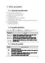
Page 8: ...cate the safety and other important matters and their specific meanings are as follows Symbols and vocabulary Meaning DANGER Indicates that a hazardous situation may occur and if not avoided may resul...

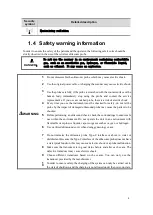
Page 9: ...ment must be checked for safety do not let the probe by the impact of damaged ultrasound probe may cause the patient to be shocked 5 Before performing an ultrasound check check the surroundings to ens...

Page 10: ...The APP software will be upgraded from time to time and new updates will be submitted by the developer If you want a better experience please pay attention to download and upgrade 6 Do not use incompa...

Page 11: ...pling agent will be solidified on the probe head which will affect the quality of the ultrasound image The probe should be cleaned and disinfected before and after each ultrasonic examination 2 Ambien...

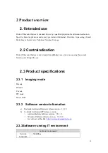
Page 12: ...not intended for ophthalmic use or any use causing the acoustic beam to pass through the eye 2 3 Product specifications 2 3 1 Imaging mode B mode M mode C mode PW mode Power mode 2 3 2 Software versio...

Page 13: ...em software security Antivirus frequency It is recommended to perform anti virus once a week to protect the system 2 3 4 Power condition Internal Battery 7 4V 1300mAh Charging power input DC 5V 2A Can...

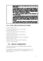
Page 14: ...Linear array C8 5Ks Slightly Convex array E10 4Ks Endocavitary array liquid condensation in the circuit board there is the risk of short circuit 3 Do not operate the unit in an environment with flamm...

Page 15: ...z 2 0 5 0MHz C5 2Ks Large convex transducer Gynecology and obstetrics abdominal kidney body surface 3 5MHz 2 5 5 0MHz C8 5Ks Slightly convex transducer Gynecology and obstetrics abdominal kidney body...

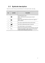
Page 16: ...part of the BF application 2 Please refer to the instruction manual for this symbol to avoid accidents 3 This symbol represents the product serial number 4 This symbol represents the date of productio...

Page 17: ...of the system Serial number Name Function 1 Transducer Transmit and receive ultrasound 2 Main Device Scanning control and data processing 3 Control Panel Operation control 4 Type C interface USB C po...

Page 18: ...er off the scanner 3 Blue blinking the scanner is in freezing status 4 Blue solid the scanner is in scanning status 2 Gain button Increase Gain and Parameters 3 Gain button Decrease Gain and Parameter...

Page 19: ...op up the probe selection dialog box Probe type Displays the currently used probe model or the default probe model Inspection type Displays the type of examination currently in use such as abdomen hea...

Page 20: ...pause to get the spectrum It s the same function as update Drop down menu flag click to enter the corresponding image mode of all parameters adjustment Image parameter adjusting pulley Slide up and do...

Page 21: ...ital Information Time Show the time that is the date and time of the system The date and time and display format preset path is preset system preset composite preset Time as the image freezes when the...

Page 22: ...area A thumbnail showing a stored image or movie under the current patient s examination Thumbnail control area Page turning When you save an image with more than one page of thumbnail click button to...

Page 23: ...rowse all patient information Ordinary account Can only manage patient information under this account First aid mode No need to log in to the password only the patient information under the account ca...

Page 24: ...ttery level indicator Two grids are always bright More than 75 of electricity One grid is always bright left 50 75 of electricity One grid is always bright right 25 50 of electricity Slow flash 25 or...

Page 25: ...apter to charge the scanner to full capacity The battery have self discharge rate about 1 one day You need to charge and discharge the scanner every month no mater you use it or not When you charge th...

Page 26: ...the display device to the scanner WARNI NG 1 The use of abnormal heating probes may burn patients 2 If any abnormality is found the probe is faulty Turn off the scanner immediately and contact the ser...

Page 27: ...ediately Android Connect the straight USB C to the scanner USB C port connect the elbow USB C to the Android device and you will get images immediately 4 Detailed operation introduction 4 1 Image mode...

Page 28: ...o dimensions by assigning a brightness level based on the echo signal amplitude To achieve the best possible image quality properly adjust the display brightness gain depth settings viewing angle and...

Page 29: ...nsated and the depth gain is adjusted in different segments Effect By adjusting the signal gain in a specific depth range the echo of the tissue image is uniform Frequency Resume The emission frequenc...

Page 30: ...ch improves the contrast resolution and reveals the location of the lesion more easily L R Flip U D Flip Resume By changing the way the image is displayed to obtain a better viewing angle the vertical...

Page 31: ...c tissue optimizations fat fluid routine and muscle 4 4 Parameter adjustment about M mode Motion mode M Mode is an extension of B mode It provides a trace of the B image displayed over time A single b...

Page 32: ...uency value is displayed in real time on the image parameter area on the left side of the screen There are three frequency modes in the fundamental wave or the harmonic wave penetrating power conventi...

Page 33: ...pseudo color maps which are effective for real time frozen and movie playback images Gray Map Resume Adjust the black and white gray scale contrast to optimize the image Effect Q7 pocket ultrasound sy...

Page 34: ...ft side of the screen provides real time parameter information which allows you to adjust the following parameters Adjustment method Parameter term Control panel adjustment Gain depth SoftKey adjustme...

Page 35: ...ustic beam in color mode thus changing the angle between the acoustic beam and the direction of blood flow is only effective for the linear array probe Wall filter Resume The low frequency noise cause...

Page 36: ...of the image evenly and the detection depth also increases Influence In clinical application proper sound power should be selected according to the actual situation and ALARA sound power principle 4 6...

Page 37: ...ain value is displayed in real time in the image parameter area above the screen Effect If the gain is too high it will amplify the noise if the gain is too low it is easy to lose the blood flow signa...

Page 38: ...ng the image parameter area on the left side of the screen provides real time parameter information which allows you to adjust the following parameters Adjustment method Parameter term Control panel a...

Page 39: ...Corresponding to the adjustable contrast range of the image the larger the dynamic range the richer the level of image display and more information but the noise will also increase Influence This fea...

Page 40: ...ange below the baseline and a negative value shows a larger range above the baseline Quick Angle Resume The correction angle is adjusted rapidly by 60 degrees step and the angle value is displayed on...

Page 41: ...on the PW image Effect It is helpful to accurately locate the time information of special points and identify the characteristic lesions in the fluctuation cycle Influence This feature is valid for r...

Page 42: ...n the ultrasound image Length ratio Measure the length of the two lines on the ultrasonic image and calculate the ratio Area ratio Measure the area of two enclosed areas on ultrasonic images and calcu...

Page 43: ...lication measuring package Obstetrical application measuring package Gynecological application measuring package Cardiac application measuring package Small organ application measuring package Neural...

Page 44: ...annotation types typing characters and indicating arrowheads 6 3 Body mark for Windows version The body position of the probe and the position of the probe scanning direction are indicated by the body...

Page 45: ...0 3 80 depth 130 2 depth 80 3 80 depth 130 2 depth 50 1 depth 50 2 depth 50 E Azimuthal resolution mm 1 depth 80 2 80 depth 130 1 depth 80 2 80 depth 130 1 depth 60 1 depth 60 1 depth 60 F Fade zone m...

Page 46: ...It can be correctly identified and there is no aliasing PW P Service frequency MHz 2 0 3 5 2 5 3 5 5 0 6 0 6 0 7 5 5 0 6 0 Q Depth of investigation mm 120 120 40 40 40 R Velocity measurement deviation...

Page 47: ...pth 60 F Fade zone mm 3 G Slice thickness mm 8 H Transverse geometric position precision 10 I Longitudinal geometric position precision 5 J Perimeter and area measurement deviation 15 K M mode time di...

Page 48: ...efore the probe is used to examine the human body Please use the probe protection sheath accepted by the market CAREF UL 1 In order to avoid infection the probe cover or sheath can be used only one ti...

Page 49: ...and fragile part collision or drop is strictly prohibited When the diagnosis is suspended it should be placed in the probe box and the instrument should be in a frozen state Medical ultrasonic coupli...

Page 50: ...al disinfection Gently wipe the probe back and forth with a medical cotton ball dipped in 75 medical grade alcohol Note on disinfectant solution As for methods of dilution concentration and disinfecti...

Page 51: ...d to immerse probe socket in any solution Probe surface is waterproof but only probe head Please be careful while using coupling agent and cleaning or disinfecting probe surface 5 Users are not allowe...

Page 52: ...o exit the puncture status 8 2 Puncture lead calibration Put the biopsy guide and transducer Acoustical lens under water Make sure the rubber of the transducer is above the water Click calibrate to al...

Page 53: ...increasingly concerned about the application of ultrasonic technique in diagnosis and may lead to the potential risk of biological effect 9 2 Caution use declaration Although there is no confirmation...

Page 54: ...he organization micro bubbles increasing vibration and the results diabrosis this reaction is called cavitation MI said the possibility of pressure cavitation effect MI value is obtained by the square...

Page 55: ...ct 9 4 2 MI TI display instructions TI and MI display on the screen of centre The operator should monitor these index values in the inspection process and to ensure that in the premise of effective di...

Page 56: ...output limit depending on the selected mode of the probe surface temperature rise and the provisions of the FDA acoustic output of each probe Be careful When you turn on the scanner change transducer...

Page 57: ...s scanning and non scanning mode the thermal effect with M Doppler Color are closely related The attenuation of the tissue is directly related to the change of the probe and its frequency The image de...

Page 58: ...play uncertainty The displayed MI and TI values are based on calculations that use a set of acoustic output measurements that were made using a single reference ultrasound system with a single referen...

Page 59: ...eeking Marketing Clearance of Diagnostic Ultrasound Systems and Transducers issued by FDA in 2008 6 Medical electrical equipment Part 2 37 Particular requirements for the basic safety and essential pe...

Page 60: ...TR 5 091 L11 4Ks Still Air Normal B C PW 22 380 23 340 TF 34 73 TR 11 390 C8 5Ks TMM Normal B C PW 24 656 25 740 TF 31 553 TR 5 813 C8 5Ks Still Air Normal B C PW 23 731 23 838 TF 38 376 TR 14 538 L11...

Page 61: ...nding national standards Cable information table Order number Name Cable length m Whether to shield or not Remarks 1 DC input power cord 1 5 yes 2 C5 2Fs Probe cable 1 5 yes 3 C5 2Ks Probe cable 1 5 y...

Page 62: ...ulation type DSSS modulate OFDM modulate Frequency characteristic 802 11b 802 11g Effective radiated power TX power 18 0dBm 1DSSS 14 5dBm 54OFDM RX sensitivity 95 7dBm 1DSSS 74 0dBm 54OFDM 10 The guid...

Page 63: ...r hospital environment Surge IEC 61000 4 5 1 kV Differential mode 2 kV common mode 1 kV Differential mode 2 kV common mode The power quality of the network must be a typical commercial or hospital env...

Page 64: ...P 80 MHz to 800 MHz d 2 3 x P 800 MHz to 2 5GHz Among them P is the rated maximum output power of transmitter manufacturers is a unit of Watt D is the recommended distance the units are in meters Thr...

Page 65: ...osed system and portable mobile RF communication equipment The following suggestions to keep the distance is calculated according to the maximum output power of communication equipment Maximum rated o...

Page 66: ...s that generate scanning lines that do not follow the same acoustic path Scanning mode Parameter B mode Gain 0 100 tunable Maximal acoustic output 10 100 tunable Depth C5 2Fs probe 30cm C5 2Ks probe 3...

Page 67: ...nces in all homogeneous materials in the parts of the SJ T11363 2006 in the specified limits requires the following The toxic and harmful substances exceeded the limitation of SJ T11363 2006 standard...

Page 68: ...ut power after attenuation P1 Bounded output power pi Pulse sound pressure square integral pr Peak sparse sound pressure pr a Peak sparse sound pressure Prr Pulse repetition frequency TI Thermal index...

Page 69: ...94 0 20 0 20 N A Index component value 0 20 N A 0 20 N A Acoustic Parameters 1 56 P mW 25 39 25 39 N A P1x1 mW 14 03 14 03 ZS cm N A Zb cm N A ZMI cm 2 58 ZPII cm 2 58 2 76 2 76 2 76 N A Other Informa...

Page 70: ...ucer Model C5 2Fs Operating Model M At surface Below surface At surface Below surface Index label Maximum index value Index component value Acoustic Parameters Other Information Operating control cond...

Page 71: ...omponent value Acoustic Parameters Other Information Operating control conditions Focus mm Depth mm Frequency MHz Table 201 103 Transducer Model C5 2Fs Operating Model B C At surface Below surface At...

Page 72: ...del C5 2Fs Operating Model B P At surface Below surface At surface Below surface Index label Maximum index value Index component value Acoustic Parameters Other Information Operating control condition...

Page 73: ...dex component value Acoustic Parameters Other Information Operating control conditions Focus mm Depth mm Frequency MHz Table 201 103 Transducer Model C5 2Ks Operating Model B M At surface Below surfac...

Page 74: ...value Acoustic Parameters Other Information Operating control conditions Table 201 103 Transducer Model C5 2Ks Operating Model B P At surface Below surface At surface Below surface Index label Maximu...

Page 75: ...e Index component value Acoustic Parameters Other Information Operating control conditions Focus mm Depth mm Frequency MHz Table 201 103 Transducer Model L11 4Ks Operating Model B At surface Below sur...

Page 76: ...ponent value Acoustic Parameters Other Information Operating control conditions Focus mm Depth mm Frequency MHz Speed Table 201 103 Transducer Model L11 4Ks Operating Model B C At surface Below surfac...

Page 77: ...component value Acoustic Parameters Other Information Operating control conditions Table 201 103 Transducer Model L11 4Ks Operating Model PW At surface Below surface At surface Below surface Index la...

Page 78: ...ndex component value Acoustic Parameters Other Information Operating control conditions Focus mm Depth mm Frequency MHz Table 201 103 Transducer Model L11 4Gs Operating Model B M At surface Below surf...

Page 79: ...t value Acoustic Parameters Other Information Operating control conditions Table 201 103 Transducer Model L11 4Gs Operating Model B P At surface Below surface At surface Below surface Index label Maxi...

Page 80: ...ue Index component value Acoustic Parameters Other Information Operating control conditions Focus mm Depth mm Frequency MHz Table 201 103 Transducer Model C8 5Ks Operating Model B At surface Below sur...

Page 81: ...e Index component value Acoustic Parameters Other Information Operating control conditions Focus mm Depth mm Frequency MHz Speed Table 201 103 Transducer Model C8 5Ks Operating Model B C At surface Be...

Page 82: ...alue Acoustic Parameters Other Information Operating control conditions Table 201 103 Transducer Model C8 5Ks Operating Model PW At surface Below surface At surface Below surface Index label Maximum i...

Page 83: ...83 Probe E10 4Ks Mode B Probe E10 4Ks Mode B M...

Page 84: ...84 Probe E10 4Ks Mode B C Probe E10 4Ks Mode B P...

Page 85: ...85 Probe E10 4Ks Mode PW...

Page 86: ...sites Wuhan Youkey Bio Medical Electronics Co Ltd No 3 6F Unit 1 North Building of Xingye Building Science and Technology Park of Wuhan University University Park Road East Lake Development District W...

Reviews: